مواد بازیافتی کلیدی برای دوام توسعه در جهان است به عنوان مثال شیشه بطری های مصرف شده برای ساخت مواد جدید استفاده می گردد.بطری شیشه های برگشتی برای ساخت بشر و.... استفاده می شود ولی بعداز چندین دفعه مصرف قابل استفاده نیستند. هرساله میزان زیادی شیشه مصرف شده تولید می گردد که قابلیت بازیافت دارند .2500000 تن شیشه زائد از سال 1995 تولید شده است اگر چه فقط 60 درصد بطری ها بازیافت شده اند.کاربرد مجدد از شیشه های رنگی سخت می باشد زیرا آنها ترکیبات شیمیایی پیچیده ای دارند وبه افزودنی های جداکننده که متنا سب با رنگ آن است نیاز می باشد.بنابراین علاقه مندی برای بازیافت شیشه های رنگی زیاد شده است. به مواد متخلخل توجه زیادی شده است زیرا به خاطر گستره وسیع سایز حفرات آن برای کاربرد های متنوعی ازجمله عایق های حرارتی و آکوستیک پایه کاتالیست ها و... استفاده می شود.رنج وسیعی از مواد متخلخل از شیشه های مصرف شده در مقیاس آزمایشگاهی وهم در مقیاس صنعتی به وسیله کلسیناسیون پودر شیشه با افزودنی هایی مثل کلسیم کربنات ساخته شدند. در طول کلسیناسیون گازهایی از جمله 2CO به دلیل تجزیه حرارتی یا واکنش های شیمیایی ایجاد می شوند.این روش برای محیط زیست خطرناک است که این به خاط گاز 2CO است.
فوم های شیشه ای به طور کل از مواد زائد ساخته می شوند که شامل شیشه بطری های مصرف شده ̡ شیشه های CRT تلویزیون ومانیتور وخرده شیشه ها وغیره می باشند. از دیگر موادزائد که برای تولید شیشه سرامیک های متخلخل استفاده می شوند سرباره کوره های ذوب وصنایع فولاد سازی یا آهن است میزان زیادی از سرباره ها از آهن جدا می شوند .این مواد به طور در کف جاده ها مورد استفاده قرار می گیرند.علاوه بر این شیشه های زائدهم برای بهبود بازیافت در فرآیند های بازیافت قابل قبول می باشد. از آنجائیکه سرباره ها وشیشه هابه طور عمده شامل ترکیبات سرامیکی هستند متدهای معمول سینترینگ برای تولید مواد منجمد از شیشه و سرباره به کار رود ولی باید مراقب انتشار دی اکسید کربن و مصرف سوخت باشیم بنابراین باید به دنبال روش های بهتری برای تولید فوم های شیشه ای از این مواد باشیم. . ریز ساختار شیشه یا سرباره گداخته شامل شبکه 2SiO است که اکسید های قلیایی وخاکی را می توان به آن اضافه نمود که در طی آن باید خواص فیزیکی وشیمیایی آن کنترل گردد مثل ویسکوزیته.
علیرغم اینکه میزان زیادی سرباره از صنایع فولادسازی وآهن و ضایعات کوره های ذوب دور ریخته می شود که این مواد به عنوان ساخت موادجدید می تواند مورد بازیافت قرار گیرد.فرآیندهای جدید برای تولید مواد با ارزش افزوده نیازمند توسعه بازیافت سرباره وشیشه های زائد است اگر چه بازیافت سرباره یا شیشه برای توسعه مواد با ارزش افزوده خیلی سخت است زیرا به عنوان مواد دارای اکسرژی پایین در نظر گرفته می شوند.اکسرژی به وسیله معادله زیر تعریف می گردد.
SΔ oT- HΔ= Exergy
HΔ:آنتالپی oT:دمای اتاق SΔ :آنتروپی ماده
ماده ای با HΔ ببشتر و SΔ پایین دارای اکسرژی بالایی است این هم به این منظور است که ماده ارزشمند ومفید است.شیشه وسرباره از ترکیبات اکسیدی چندتایی تشکیل شده است.اکسیدها از فلزات خیلی پایدارترند.علاوه برآن شیشه وسرباره که مخلوطی از کاتیون وآنیون هاست دارای آنتروپی اختلاط بالایی است.بنابراین شیشه وسرباره اکسرژی پایینی دارد.ازاین رو به خاطر پایین بودن اکسرژی شیشه وسرباره برای تولید مواد با ارزش افزوده از طریق بازیافت سخت می باشند.
ما در بحث بالا فرض کردیم که مواد سایز نامحدود و ساختار یکنواختی دارا می باشد.اگر سطوح یا فصل مشترک در داخل ساختار ترکیب شود ماده می تواند ارزش افزوده به خود بگیرد وکاربردی باشد.برای نمونه وقتی شیشه یا سرباره رابسازیم که در شکل 1نشان داده شده است می توانیم آنها رادر شیوه های مختلفی به خاطر پدیده های سطحی آن به کار بریم همانند فیلتر ها وجاذب ها.
صنعت مواد متخلخل با سرعت زیادی پیشرفت کرده است که این اتفاق به خاطر کاربرد های فراوانی که این مواد دارند. مواد متخلخل با حفرات بسته یاباز در روش معمولی با سنتز ترکیب ماده جامد وتجزیه همزمان ترکیبات آلی مانند کلسیم کربنات ساخته می شدند. این پروسه در حین فرآیند پخت اتفاق می افتد که باعث شکل گیری تعداد زیادی حفره در ساختار سرامیک می گردد. از دیگر روش هایی که برای تولید شیشه سرامیک های متخلخل به کار می روند عبارتند از: تبدیلات فازی وgelcasting. به طور کلی همه روش هایی که برای تولید شیشه سرامیک های متخلخل مورد استفاده قرار می گیرند شامل افزودنی های آلی وسمی می باشد و فرآیند گران قیمتی است زیرا یک روش مخصوص برای کنترل تخلخل ها نیاز است.
Batch Charging Equipment
Today Frazier-Simplex, Inc. remains the premier designer and manufacturer of batch charging equipment throughout the world. Many of our batch chargers are still performing this most critical of functions since being installed in the 1960's.
Frazier-Simplex, Inc. originated the blanket batch charging concept in the 1940's and continued the expansion of batch charging technology by the introduction of the use of screw batch chargers shortly thereafter.
Today, screw batch chargers remain the first choice for all Oxy-fuel fired furnaces the world over as well as in other applications.
If the conventional blanket batch charger or the screw batch charger is your selection, Frazier-Simplex stands prepared to supply your requirements. Conversely, should your batch charging requirements call for a custom design or solution, Frazier-Simplex would be more than happy to discuss your needs.
Examples of our custom batch chargers include:
-
Doghouse mounted blanket batch chargers
-
Table top precision screw chargers
-
Ram type pusher batch chargers
-
Revolving scoop indexing batch chargers
-
P.O. Box 493, 436 E. Beau St.
Washington, PA 15301
Ph: (1) 724.225.1100
Fax: (1) 724.225.4429
glass@frazier-simplex.com

محمد وکیلی با مدرک فوق دیپلم و از نفرات بسیار قدیمی صنعت شیشه تخت ایران می باشند و مسئولیت تعداد زیادی از نسوزچینی های کوره های شرکت ابگینه را برعهده داشتند
مهندس مواسات فارغ التحصیل در رشته مواد و سرامیک از دانشگاه علم و صنعت که سابقه چندین دوره نسوز چینی در شرکت آبگینه قزوینُ صنایع شیشه فلوت آذر و گروه صنعتی کاوه را دارا می باشند ایشان هم اکنون مدیریت تولید کارخانه شیشه آبگینه را بر عهده دارند.
مهندس معین افشار ،مهندس شیمی و فارغ التحصیل از دانشگاه منچستر که زحمات فراوانی در شیشه قزوین در زمینه ساخت و راه اندازی و درگروه صنعتی کاوه کشیدند و به عنوان نفرات شاخص در این صنعت شناخته میشوند ایشان هم اکنون سمت مدیریت کارخانه شیشه فلوت لیا را بر عهده دارند
مهندس اسلامی مهندس شیمی و فارغ التحصیل از دانشگاه شریف با سابقه بیش از ۳۰ کوره ساخت
وتعمیرات به عنوان معروفترین فرد در صنعت شیشه ایران و مورد تایید شرکت هایی معروف همچون زورگ
میباشنداز سوابق ایشان میتوان به تدریس در دانشگاه علم و صنعت و ساخت کوره هایی در شرکت
هایی نظیر آبگینه قزوین،لامپ مهتاپ،شیشه فلوت آذر،سهند جام ،زاب سان و ده ها شرکت دیگر
شیشه سابقه درخشانی در این صنعت دارند.
Modulating Burner Combustion Control for Glass Furnaces and Forehearths
Fossil fuel burners are often used as the principle medium for delivering energy to industrial furnaces and ovens.
Increasing focus on reducing energy costs has led manufacturers to concentrate on new burner design techniques and important advances in efficiency gains have been made over the years. Burner management and control systems must be equally adaptive.
Eurotherm® provide efficient, well implemented control techniques capable of reducing operating costs whilst providing resources for greater flexibility in plant anagement and control. Burner combustion generally includes one or a combination of the following methods:
-
Regulation of excess air
-
Oxygen trim
-
Burner modulation
-
Air/fuel cross-limiting
-
Total heat control
Excess air regulation
In actual practice, gas, oil, coal
burning and other systems do not
do a perfect job of mixing the fuel
and air under the best achievable
conditions. Additionally, complete
mixing may be a lengthy process.
Figure 1 shows that in order to
ensure complete combustion and
reduce heat loss, excess air has to
be kept within a suitable range.
The regulation of excess air provides:
-
A better furnace heat transfer rate
-
An 'advance warning' of flue gas problems (excess air coming out of the zone of maximum efficiency)
-
Substantial savings on fuel
Oxygen trim
When a measurement of oxygen in the fuel gas is available, the combustion control mechanism can be vastly improved (since the
percentage of oxygen in the flue is closely related to the amount of excess air) by adding an oxygen trim control module, allowing:
● Tighter control of excess air to oxygen setpoint for better efficiency
● Faster return to setpoint following disturbances
● Tighter control over flue emissions
● Compliance with emissions standards
● Easy incorporation of carbon monoxide or opacity override
Burner modulation
Modulation control is a basic improvement in controlling combustion.
A continuous demand signal is generated by a controller monitoring
the furnace atmosphere.
Reductions in temperature lead to an increase in firing rate. The
advantages of introducing burner modulation in combustion control
include:
● Fuel and air requirements are continuously matched to the
combustion demand
● Furnace temperature is maintained within closer tolerances
● Greater furnace efficiency
● Weighted average flue gas temperature is lower
At the fall of 2006 Asahi India celebrated “ first glass” from its 700 tonnes new float line in Roorkee. It was a spectacular moment for the Eurotherm glass team that saw its 2.800 I/O point Batch House Automation system come to life, and deliver the first batches of raw material to the melting furnace. It is from that moment that Eurotherm involvement changed from system conceptual design, detailed engineering, cabinet building, system programming, testing and installation and commissioning to actual silo and hopper filing, batch weighing, batch transport, mixing and cullet returns.
The batch process of the float line has been divided into four sections. Each of the sections, or process cells, can be controlled either from the Distributed Control System (DCS) or from the Local Control System (LCS).
Silo feeding
This consists of feeding the raw matarial into one of eleven silos or hoppers. When unloaded from the trucks raw material is conveyed through a series of bucket elevators and conveyor belts to the silica, soda ash, limestone, feldspar or sodium sulphate silo.
Each of these silos are fitted with level transmitters, pressure switches and over pressure flaps that are all mounted and controlled by the EurothermSuite DCS System. The silos have a series of dedusting units that help in trapping the excess dust, which tends to rise as the silos get filled up. These dedusting units comprise of dust collectors and blower fans. At
every stage magnetic separators prevent iron impurities finding their way into silos.
Batch weighing and transport
This section deals with the weighing, dosing and transport issues of the batch plant. Dosing into the weigh scales is either through screw feeders, pneumatic feeders or vibrating feeders.
Both coarse and fine dosing from the feeders into the weigh scales is controlled by Eurotherm AC inverters. The time and sequenced dosing of the raw material is completely controlled by the EurothermSuite System.
The conveyors are again controlled by Eurotherm AC inverters.
Mixers
The plant is equipped with two mixers each driven by a 110kW motor that is controlled with a Eurotherm flux vector AC drive. Raw material is fed to the mixer that has to be filled through a swivel pipe. The EurothermSuite System also controls the elaborate water
and oil feeding options that are used to ensure that the mix reaches the desired consistency before it is fed on to the main conveyor belt.
Cullet is added to the mix on the conveyor belt to get the final mixture that is ready to be loaded in the furnace. When the final mix is not of the desired quality it is rejected and fed to a waste hopper.
A four compartment batch charger takes the final mix to the furnace silo from where it is fed into the melting furnace.
Cullet and cullet return
As with almost every glass producer, Asahi is using cullet from external suppliers or cullet that is returned from its own production line. The cullet handling part of the control system deals with the loading of the cullet silo with material of the cullet yard as well as
the cullet crushing and return from the float line.
Eurotherm AC inverters control the operation of line crushers, water crushers finger drops and breakers as well as the conveyor
belts that transport the cullet directly back into the batching process or to the cullet yard.
Incoming cullet from external sources is loaded into a hopper that feeds the cullet to a series of crushers. On its way to the cullet silo the cullet passes magnetic detectors and magnetic separators that keep iron parts away from the silo and finally from the raw glass melt.
Safety
From a safety point of view the systems supplied are in compliance with all the relavant safety and machine directives. Emergency stop switches, pull cord switches zero speed detector units and belt sway detectors secure to bring the plant into a safe state when an
emergency does arise.
Eurotherm supply
Eurotherm has been responsible for the design, delivery, installation and commissioning of the DCS System and the motor control systems.
The EurothermSuite DCS System comprises of:
5 off T940X Process Supervisor (redundant)
33 off Model 2500 Process I/O units for 2,800 I/O signals
2 off Operator workstations - EurothermSuite Operation Servers
5 off Local operator stations
The model 2500 I/O units communicate with the T940X Process Supervisors via Profibus DP, whilst communication between the T940X’s among each other and the Operator workstations uses a redundant fibre optic Ethernet ring.
The motor control system comprises of 10 Eurotherm 690 Series AC inverters in a range of 10kW to 110kW. The inverters are fully integrated with the PCS system Process Supervisor using a Modbus RTU connection.
The process to allow you to benefit from these control improvements
-
Review of your requirements
-
A technical evaluation of your process
-
Analyse results from above
-
Eurotherm will prepare economically and technically attractive systems
Advanced Laser Technology for Glass
 |
The method of cutting and breaking in order to seperate glass is as old as the material itself. This separation method, which is still predominantly used today, underwent a revolution at the beginning of the 20th century, when cutting wheels were invented. The next relevant evolutional step in glass separation was the use of laser radiation to cut glass products. Laser processing of glass shows, especially in the area of the high-tech products, clear advantages compared to separation by cutting wheels. |
Here the principle and results of using NIR-Laser radiation for separating flat glass and laminated glass will be shown. The delineated characteristics of the process lead to an advanced laser based glass cutting machine. This laser method enables to cut without mechanical forces and with high reproducibility. Complex 2D geometries, which can be conventionally manufactured only by using time intensive grinding and polishing procedures, can be realized in one processing step with the help of laser technology. Laser cut edges attain a quality comparable with those of conventionally polished edges. The laser separated edges are convincing due to a high mechanical stability and thermal shock resistance. Thus, lasers are one of the most interesting high potential tools which can be easily automated in high-tech glass processing.
Flat glass is cut predominantly by scratching and breaking. This process produces splinters of glass fragments and micro-cracks along the separation line, respectively distortions of the separation edges. Micro cracks are in many cases starting points for further damages of the product and its failure. Glass fragments can cause scratches on glass surfaces or already applied coatings. These influences can reduce the quality of the product up to the uselessness of the product. To remove micro cracks in many cases the edges in additional work through to grinding and polishing have to be improved. These processes mean a further post processing and require further cost and time-intensive cleaning of the product of working debris. The process of separation with high-quality edges can be reduced to one process step with the Multiple Laser Beam Absorption method (MLBA), the full body laser cut.

The Process
Nearly all cracks in glass are induced by tensile stress at the glass surface. Due to this effect the cooling of glass is more critical than heating up. Using this effect, a laser based glass cutting technology has been developed to guide thermal induced cracks through the glass. The MLBA process is based on the multiple reflection of laser radiation. Within this process, NIR-lasers in the high transmissive range of glass smaller than =2.000 nm are used. The best results are realised with conventional industrialƒÜ =1.030 µm or 1.064 µm. TheƒÜlasers emitting radiation of the wavelength radiation of this type of laser, depending upon glass thickness and type, is transmitted up to 90 %. In the glass present ferric oxide is considerably responsible for the absorption of NIR-laser radiation. Regarding the effect that nearly 4 % of the radiation is reflected at each glass surface, the total absorbtion can be calculated by the following formula.
100%=Transmission + Reflection + Absorption
In contrast to the CO2 laser glass cutting methods, where the radiation is nearly totally absorbed at the glass surface, the NIR-Laser causes due to the low absorption an increased temperature over the whole treated glass volume. Multiple reflection of the beam through the product provides a sufficient absorption and good efficiency.
One special effect by laser heating of glass is the locally variation between the laser cross section and the point of highest temperature at the glass surface. This distance is variating by the feed rate of the laser beam and causes special solutions in controlling the maximum glass temperature during complex cutting operations.
The crack results from stress differences in the glass material and the surfaces. In the heating phase, the laser beam creates compressing stress over the whole glass thickness. Cooling the surfaces by free convection to air causes a tensile-compression-tensile stress profile without using any cooling fluids. The crack caused by the thermal tensions perpendicularly to the main stress level propagates beginning at an initial crack. The stress levels can be calculated as follows:
s= DT a E/(1-m)
Where E is Young´s is the thermal extension coefficient and µ is the Poisson's ratio. isƒÑmodulus, the temperature difference caused by laser heating. During the cutting process, locally limited and precisely adjustable heat fields are created and controlled by the laser beam. The heat fields lead the crack, through the product.
The process parameters for cutting depend on several factors. The geometry of the raw material and of the laser path are relevant for the needed mechanical forces to separate the products. Glass parameters as the absorption are relevant for the necessary laser power. Further the laser beam caustic and mode are relevant settings for the energy density and distribution.
The shape of the raw material has a substantial influence on the maximum separation speed. With linear, symmetrical separation processes the relationship from sample width to sample length is crucial. The needed tensile stress to induce the crack is depending on the mechanical stiffness of the work piece. For example, by using 8 mm thick glass with always the same length and increasing the relation of length to width by the eight fold, the maximum separation speed can be increased by 28%. The more narrow the raw material is, as faster it can be cut. This measured variable is also crucial for the separation of complex outlines, where the relationship of the sample dimensions for the momentary separation process can vary strongly with its position.
For cutting laminated glass, the optimal deposition of energy per distance is very important. Too much energy causes an uncontrolled cracking of the Glass plates because of the stress in the foil, induced by the laminating process. Insufficient energy is responsible for the crack stopping on its way through the glass. Parameters are also different for certain materials, glass thicknesses and coatings.
One factor influencing the maximum cutting speed is the used energy per section. A delay between the initial heating of the glass due to the laser propagation and the maximum glass temperature can be realised. Thereby it was necessary to evaluate if this delay has an influence on an increasing cutting speed. The following diagram shows, that the use of more laser energy is inducing a higher maximum cutting speed. Because of the linearity of this effect the energy per section for reaching the maximum cutting speed is constant. Following from this it can be declared, that in the evaluated scope the delay in heating up the glass is not a relevant factor for an increasing cutting speed by using a higher power level. The curve is limited in the maximum laser power because of back reflection. It is liable that the cutting speed increases by the use of higher laser power.
The surfaces of the separated edges with MLBA technology exceed the quality of mechanically polished surfaces and increase additionally the firmness of the products. The roughness of a laser cut edge can be found in a range of Rz DIN = 0.034 µm to 0.038 µm according to measurements with ATOS PLµ. Bending tests showed that laser cut glass products had an up to 2 time’s higher firmness than conventionally cut samples. Thereby thermal hardening processes without rework of the glass edge are possible. From the emission-free process arise advantages, which promise a successful use in the manufacturing of high-tech products. Glass fragments, abrasive dust and the necessary cleaning processes are to be avoided by the processing of coated glasses, which is not only an economic argument for the laser process. The contactless separation in one working step without auxiliary materials in an industrial standard is made possible for the first time with this technology.
Due to the volume absorption several stapled glass plates can be separated in one processing step without the usual breaking process. Also bonds, like for example laminated glass, can be cut in a defined way. Further selective cutting of individual, single glass sheets in a multi layer stack, as for example contact steps in an electrical heated windscreen, is possible. The process can be used for all soda-lime glass, including coated rear view mirrors and ITO-coated glass.
The economical view shows that the total process times of conventional separation processes in connection with grinding and polishing processes, cleaning and transport of the glasses, exceed the operating time of the MLBA process. Product samples which have already been manufactured with this technology are tachograph coversheets, rear-view mirrors and side window samples. Further products, which can be manufactured economically with this technology, are for example display glasses, solar cells cover plates, as well as design glass products.

In the area of automotive glass processing the cutting of windscreens could be an interesting application. Windscreens and side windows more and more move to complex 3-D construction parts. Because of the increasing area of glass in modern car bodies the windows have to fullfill bracing tasks. The processing of these products could be done with the use of robots for a flexible production. This configuration is not stated by defined mirrors, but can be programmed to cut different contours in one line. One robot for handling the glass sheet and one for moving the laser head relative to the product.
Conclusions
The laser beam as a tool for separating glass materials is already introduced in modern industrial processes. Examples are laser beam scratching of display substrates as well as the laser beam blasting of glass tubes. Laser processes become economically interesting in mass production as well as for manufacturing high tech products. Over the shortened process chain investments in the laser source amortize at a short time. The laser possesses the potential to replace the cutting wheels within wider areas of manufacturing high tech glass products.
http://www.conceptpatterns.com/glass-industry-news/advanced-laser-technology-for-glass.html
|
|
| |||||||
|
|
| |||||||
|
|
|
The JF Swinehart Co., Inc. PO BOX 510 OHIO TELEPHONE 419.435.6013 ● FACSIMILE 419.435.0528 E-MAIL jfs@jfswinehart.com | ||||||
|
|
|


Integrated Controls Automation Enables High-Speed Float-Glass Stacking
(posted 02/18/2010)
 Grenzebach automates new High-Speed Stacker with Siemens SIMOTION motion control and SIMATIC PLCs fully integrated into one system, for increased throughput, reduced production costs, better finished glass quality and improved safety.
The float glass industry is facing multiple challenges, not the least of which is a growing array of applications requiring a broader offering of products and sizes, and competition from offshore producers.
The need for more flexibility and speed in the production process has never been so important. Similarly, the necessity to reduce production costs and optimize profit margins has never been so critical. Smart glass producers are finding that replacing manual functions with streamlined automation is not only meeting these objectives, but also has become a requirement for long-term stability and success.
Of all the functions on the float glass line, stacking remains the most labor intensive, and therefore a key target for automation. Glass producers have been looking for a more efficient, reliable and cost-effective method to stack the expanding selection of glass sizes they manufacture. Some producers have automated their stacking, but have experienced difficulties with speed of throughput, because of glass stacking displacement causing breakage.
But many more float glass producers are still handling stacking manually without the aid of any controls automation.
Fully automated cold-end line
Effectively streamlining the uniformity and quality in the making of plate glass - a new generation of glass-handling equipment has emerged, which is destined to change the landscape of cold-end line process efficiencies. Developed by Grenzebach, in tandem with Siemens, a new line of glass-handling equipment is being released featuring integrated controls systems that provide a fully automated solution to the handling of finished float glass. Every function of the cold-end line is being integrated into one controls automation platform – including take-over of the glass from the lehr, cutting the glass ribbon into sheets of optimum size, glass snapping, rejection of faulty glass sheets, sorting according to size and quality, and stacking into glass racks with robotics.
The cold-end line requires that multiple, continuously-operating functions be precisely and sequentially connected. Grenzebach and Siemens have effectively brought each of these functions into one complete and totally integrated automation controls system, with the net effect of reducing production costs and increasing throughput. This package of automation controls is equally applicable to individual machines in the line, so additional line equipment can easily be added to the system at the discretion of the plant.
Grenzebach
Grenzebach is a pioneer in float glass cold-end equipment. In 1974, the company developed the world’s first processing systems for automated float glass production. In addition to machines for transport and handling operations, and cutting and breaking lines, systems for identifying flaws, glass quality control and optimization of material yield have also been created.
Grenzebach Corporation is the U.S. subsidiary of Grenzebach Maschinenbau GmbH of Hamlar, Germany, which is a global manufacturer of production equipment for the flat glass and construction material industries. It is recognized as an international mechanical engineering company, with development and production facilities in Germany, the United States and China. Worldwide, the Grenzebach Group has some 1,400 employees.
High-Speed Stacker
The first piece of Grenzebach equipment to exclusively utilize this advanced automation technology is the company’s new High-Speed Stacker. Designed to increase glass manufacturer’s efficiency and flexibility, it was developed for stacking small glass formats with high cycle times, and is currently the only device which can stack glass sheets in less than a one-second cycle. The new system is the world’s most flexible glass stacker.
It is a robot-assisted float glass stacker, which reaches its speed from quickly forming sub-packs of glass and achieves its flexibility by stacking the sub-packs with a robot. The system improves employee working conditions and stacking accuracy and efficiency, while decreasing product damage and ultimately costs. The High Speed Stacker is an ideal answer to today’s flexibility and speed demands in the glass manufacturing industry.
 The High-Speed Stacker stacks glass formats from 12” x 18” up to 73” x 97”, and then transports glass sheets by a suction belt into a packet frame, where each sheet is placed successively until a sub-pack has been created. Next the packet is transported to a robot for take-off, either from above or from the side, to be stored on a glass rack that is used to transport the product to other facility locations or to end customers.
The system’s six-axis robots are capable of correcting the stacking alignment and creating precise glass stacks. For small glass sheets, two packets are built up and stacked parallel. Using this production method, up to 80 glass plates per minute can be taken off and stacked. The robots have a payload capacity of up to 220 lbs. and also feature integrated energy supply systems to reduce floor space.
The stacker can stack multiple sizes of glass with varying orientation - landscape or portrait, tin side in or tin side out with accuracy and speed. The High-Speed Stacker offers manufacturers the flexibility to adapt to product variations and rack and equipment changes. Feeding can be performed in a double stream, so that two packets are built up and stacked in parallel. It can be integrated into existing side-legs, but also demonstrates its stacking qualities in off-line cutting operations.
High-Speed Stackers can automate the entire packing capacity of a typical float glass production line, and can completely eliminate manual packing of glass.
Ideally, the angle of the glass rack is known and accurate. Since glass is heavy and the racks are being exposed to rough handling during regular operations, this angle can change over time compromising the structural integrity of the rack. As a result, a conventional stacker would not stack the glass in an optimal manner and glass breakage could occur. The robot of the Grenzebach High-Speed Stacker scans the rack for dimensional and angular discrepancies and adjusts its stacking program according to the actual geometry of the rack.
“Our customers have been demanding a better solution for stacking the many different glass sizes that they manufacture,” says Gerald Haas with Grenzebach Corporation. “Until now, they have had to rely on manual labor for their stacking operations. With the High-Speed Stacker, not only do they improve their employee’s working conditions, but they increase their operational efficiency and flexibility.”
Totally Integrated Automation
Grenzebach’s totally automated cold-end line, and specific application to the High-Speed Stacker, is functionally based on Siemens’ concept of Totally Integrated Automation (TIA). TIA is characterized by its unique continuity. It provides maximum transparency at all levels with reduced interfacing requirements. It encompasses the field level and production control level, up to the corporate management level.
It also provides maximum interoperability, covering the controller, HMI and drives, up to the process control system. This reduces the complexity of the automation solution in the plant.
Motion Control, PLCs and Tech functions in one system
Central to Siemens’ TIA system in place with the Grenzebach line and High-Speed Stacker is SIMOTION®, Siemens latest generation of motion controller. SIMOTION, which includes a palate of high-tech control system components which are optimally harmonized.
Most machines require motion control (positioning, synchronous operation), PLC functionality and technology tasks (i.e. pressure control and temperature control).
The fusion of these functions into one system - as with SIMOTION - has a number of advantages, such as lower engineering costs, higher machine performance, the elimination of time-critical interfaces between individual components and simple, uniform and transparent programming and diagnostics for the entire machine with a single tool. The focus here is placed on a simple and flexible solution for numerous motion control tasks.
The motion controller, the drives and the motors encompass the scope of the Grenzebach cold-end line needs. This was a very big step forward technologically for Grenzebach, in terms of the wiring, drive integration and motion control. Taking standard, off-the-shelf Siemens technologies and applying them to a machine solution presented significant advantages to Grenzebach as an OEM.
Integrated with SIMOTION is Siemens SIMATIC® S7-300 automation system. Applicable for centralized and distributed configurations, it has the ability to integrate powerful CPUs with Industrial Ethernet/PROFINET interface. It can be set up in a modular configuration without the need for slot rules with I/O modules.
The Siemens SIMOTION motion control and SIMATIC controller provide a fusion of motion control, PLC and technology functions in one unit. This means that the new sophisticated stacking robots in use with the High-Speed Stacker can now be more easily controlled and operated.
Improved safety
A critical requirement of machine manufacturers and operators is seamless safety between humans and machines.
A truly safety-integrated system is a complete and consistent safety portfolio, which covers all tasks to be accomplished in the field of safety technology – ranging from detecting through evaluating, to reacting. In float glass production, safety is a critical concern. The automation built into the Grenzebach system greatly increases safety with handling sheet glass, resulting in far less accidents and injuries.
The Siemens S7 controllers are SIMATIC Safety Integrated, which provide the highest level of safety for humans, machines and environ¬ment. They are used to prevent accidents and damage resulting from a fault or mal¬function. The safety SIMATIC controllers monitor themselves, detect faults autonomously and immediately change into or remain in a safe mode when a fault occurs. They are optimized for use in production engineering and provide air-tight safety for all operations.
Fail-safe CPUs have been exercised for safety-oriented applications with the Grenzebach High-Speed Stacker and all other equipment on the cold-end line. The PROFIsafe profile for safe communication via PROFIBUS and PROFINET allows the integration of safety-related functions into standard automation environments.
Automation for a changing market
“We are making the SIMOTION and SIMATIC technology available to float glass producers so they can benefit from its system-wide controls capability and streamline their cold-end line production,” says Chad Shaffer with Siemens.
“This totally-integrated solution has been successfully applied to many other industries, but it is quite unique to float glass production until now.”
“Siemens has teamed with Grenzebach to help effect production efficiencies in the glass industry,” continues Shaffer. “More efficient equipment, safer production systems and a better bottom line for glass producers are our objectives.”
As glass producers deal with the influence of an increase in cheaper off-shore glass being imported and a more diverse product mix, production automation is more important than ever before. With new equipment providing better solutions, like the High-Speed Stacker equipped with a truly integrated controls package, glass fabricators stand in a much better position to operate their plants more efficiency and maintain a more competitive stature in the market.
About Siemens
Siemens Industry, Inc. is one of Siemens’ operating companies in the U.S. Headquartered in the Atlanta suburb of Alpharetta, Ga., Siemens Industry, Inc. manufactures and markets one of the world’s broadest ranges of electrical and electronic products, systems and services to industrial and construction market customers. Its technologies range from circuit protection and energy management systems to process control, industrial software and totally integrated automation solutions. The company also has expertise in systems integration, technical services and turnkey industrial systems.
Siemens AG (NYSE: SI) is a global powerhouse in electrical engineering and electronics, focusing on the three key sectors of healthcare, industry and energy. Founded 160 years ago in Germany, Siemens AG reported sales of $96.6 billion in fiscal year 2007 (ended September 30). Siemens today employs more than 470,000 people in some 190 countries.
In the United States alone, Siemens had sales of over $25 billion (including export sales), fueled largely by infrastructure projects and innovative solutions in the industry areas of medical, automation and control, power, transportation and lighting. Headquartered in New York City, Siemens in the U.S. employs nearly 72,000 people in all 50 states and Puerto Rico. The U.S. is also home to the global headquarters of nine of Siemens’ worldwide businesses.
For more information on Siemens in the United States, go to: www.usa.siemens.com
For more information on Siemens automation solutions please contact: Siemens Industry, Inc.
5300 Triangle Parkway, Norcross, GA 30092 Phone: 800-964-4114 or visit the website at www.usa.siemens.com
Grenzebach Corporation
can be reached by contacting:
Stefan Grenzebach, President & CEO
10 Herring Road, Newnan, GA 30265 Phone: 770-253-4980
www.grenzebach.com
Grenzebach is a pioneer in float glass cold-end equipment. In 1974, the company developed the world’s first processing systems for automated float glass production. In addition to machines for transport and handling operations, and cutting and breaking lines, systems for identifying flaws, glass quality control and optimization of material yield have also been created.
The first piece of Grenzebach equipment to exclusively utilize this advanced automation technology is the company’s new High-Speed Stacker. Designed to increase glass manufacturer’s efficiency and flexibility, it was developed for stacking small glass formats with high cycle times, and is currently the only device which can stack glass sheets in less than a one-second cycle.
For more information:
Siemens Industry, Inc.
Drive Technologies — Motion Control (Production Machines)
390 Kent Avenue
Elk Grove Village, IL 60007
Phone: 847-640-1595
Fax: 847-437-0784
Web: www.usa.siemens.com/cnc
Attention: John Meyer, Manager, Marketing Communications

Opened in summer 2006, the new "E-GLASS" float glass line in Germany is the first Float Line world-wide to constantly use a laser system instead of the traditional cutting wheel for edge trimming of all glass thickness up to 20 mm at the continuous glass ribbon.
This Grenzebach – development is based on the unique
LiST – technology (www.list-info.de).
- The easy-to-set float ribbon laser cutting unit does not suffer from any stress-problem.
- No pre cut is required, so that the ribbon width can be reduced.
- Any glass thickness is easy to break on the automatic edge trim deck, thus saving labour cost.
- Even extreme change of glass thickness does no longer result in cutting loss.
- The laser-cut generates oil-free and smooth edges, free of any micro-cracks.
- Scratches are avoided, raw material is saved and breakage on the line as well as thermal fractures on the racks are reduced.
- The breaking strength of the laser cut glass plates surmounts by far the average of the other flat glass on the market.
Such benefits in glass quality will set new standards and will make the new laser cutting technology a vital component of glass production and processing lines, world-wide
Tin Bath Atmosphere Recycling
Nitrogen / Hydrogen Atmosphere Recycling System For Tin Baths In Float Glass Plants 
What is it?
The recycling system is a further development toward tin bath atmosphere quality improvement. Instead of venting the atmosphere outside the tin bath, the mixture of Nitrogen/Hydrogen is pumped out continuously, purified to fresh N2/H2 specifications and re-injected back into the tin bath.
The tin bath atmosphere is extracted at several points on both sides of the tin bath casing. As the tin bath atmosphere is hot, the gas is cooled down for further processing via heat exchangers.
Then the cooled gas passes through a first filtering assembly where the main particles are trapped before being pumped and discharged to H2S removal columns.
After having passed through the H2S removal columns, the gas is filtered again and then fed to the Oxygen purifier device where oxygen content is removed from the gas.
The water particles and vapor are removed via a chemical dryer. The purified gas is then cooled down, filtered and re-injected into the tin bath atmosphere.
Facts about tin bath atmosphere recycling
We have conducted an evaluation of more than 20 float lines in operation with and without recycling system to determine the influence of the recycling system.
Below are summarized the main conclusions:
-
A recycling system allows to recycle up to 50% of the total fresh atmosphere injected in the tin bath (N2 + H2). Up to 70% of the atmosphere can be recycled in some cases. This means that if a total 2000 Nm3/h N2 + H2 is injected in the atmosphere, with a recycling system only 1000 Nm3/h are needed as fresh supply and the other 1000Nm3/h are recycled for a constant turnover ratio.
-
The H2 is recycled as well. If the N2 contains for example 7% H2 at the recycling inlet, the output recycled N2 will have minimum 6.5%H2 with 0,5% being losses in the deoxo to reduce the O2 ppm.
-
All tin defects included as a percentage of total defects in glass were from 9,5% to 15% in float lines without recycling as compared with less than 0,5% in lines with a recycling system.
-
Tin baths without a recycling system add each year 4 to 5% of the total amount of tin to compensate for tin losses, dross and evaporation as compared to less than 1,5% with tin baths equipped with a recycling system. The dross is reduced significantly with a recycling system.
-
Drips, micro drips, top specks are reduced to virtually zero in tin baths with recycling systems. This compared to 40 to 90drips in average for 10m2 of glass in tin baths without recycling system.
-
Tin baths with a recycling system work with pressures less than 20 Pa as compared to higher pressures in other tin baths.
-
The N2 turnover in a tin bath with recycling can be increased 2 to 3 times more than in other baths (N2 turn over means how many times per hour is the N2 inside the tin bath completely replaced with fresh N2. Good practice recommends minimum 3 to 5 times per hour total N2 turnover).
-
The bigger N2 turnover has a great effect on glass quality and can only be achieved with a recycling or extraction of N2 without significantly increasing the amount of fresh supply.
-
Tin baths with a recycling system have decreased the concentration of H2 in nitrogen from 8 to 9% down to 4 to 5%. As a result they use two times less H2 and recycle up to 50% of the injected H2.
-
Tin bath roof and cooling equipment is cleaned up to 30 times a year in tin baths without recycling. This compares to less than 6 times a year in tin baths with recycling.
-
Cooling capacity in the float bath is reduced by approximately 20% ( less flat coolers are used)
-
The recycling can be installed or retrofitted any time during production without generating production losses or deteriorating glass quality. It is typically done during a change of thickness or color.
-
The recycling is a must for tin baths with intra float beams used for CVD (Chemical Vapor Deposition) inside the tin bath.
Space requirements
See the sketch below with the dimensions and space requirements. All dimensions are in mm. Minimum height required under the tin bath is 3000mm. Other heights can be accommodated, to be discussed.

How much will you save ?
Savings in N2 fresh supply
In normal production depending on the float line capacity, an average of 1500 to 2000 Nm3/h of pure N2 is supplied to the tin bath roof. With a recycling system, at least 50% of this flow is recycled back in to the tin bath reducing the fresh supply in half. (this does not take into account production savings due to minimum tin bath roof blow off, five to ten times less frequent cleaning of the equipment around the tin bath etc.)
Savings in H2 fresh supply
In normal production depending on the float line 150 to 200 Nm3/h of H2 is supplied to the tin bath roof. With a recycling system this will be reduced by at least 30 to 50%.
Production savings due to improved quality
Production loss due to tin bath defaults is specific to each plant and it is not possible to quantify without plant specific information.
The chart below shows the impact of a recycling installation on tin bath drips in an actual plant in France:

How much it costs?
The recycling system is tailored to each float glass plant and the cost will be dependent on many parameters that are inherent to each plant. Our specialist will be glad to make a detailed quotation for each specific case.
Depending on the budgetary constraints, plant size, lay out and configuration of each particular plant, there are several alternatives, however the most common are:
-
Option 1: Turn key installation. The budgetary cost will be 2 to 2.5million USD
-
Option 2: Supply of equipment only. The plant makes all utilities (civil works, electrical, piping, etc.) interconnections on site itself under the supervision of our engineers. The budgetary cost will be 1.5 to 2 million USD.
-
Option 3: We install the recycling system at our own cost. The plant pays for the amount of recycled gas supplied into the float bath by the recycling system and for utilities cost.
The price of recycled gas will be the same as the price paid for the fresh supply.
This is the most optimum solution as the recycled gas is equal to the amount of reduced fresh supply which the plant won’t have to pay to the supplier of N2/H2.
Basically it costs nothing to the plant, but it brings tremendous advantages in quality improvement and tin bath operation. In order to qualify for this option, the amount of recycled gas must be greater than 700Nm3/h. (fresh supply of 1200Nm3/h or greater)
Utilities and consumptions
Following would be the required utilities consumptions for a standard recycling equipment
Total electrical power
| 1. Supply | : | 400 volts, 50 / 60 cycles | |
| 2. Installed Electrical Load | : | 300 kW | |
| 3. Electrical Consumption | : | 150 kW/h | |
| 4. 3 - phase power cable from your mains to our electrical cabinets | |||
Chilled Cooling water for Deoxo
| 1. Supply Temperature | : | 12°C | |
| 2. Supply Pressure | : | 2 to 5 bars | |
| 3. Flow Rate | : | 20 m3/hr | |
| 4. Pipe Size | : | ND80, Flanged | |
| 5. Cooling Water Outlet T°C | : | 10°C temperature rise |
Chilled Cooling water for blower
| 1. Supply Temperature | : | 12°C | |
| 2. Supply Pressure | : | 2 to 5 bars | |
| 3. Flow Rate | : | 5 m3/hr | |
| 4. Pipe Size | : | ND50, Flanged | |
| 5. Cooling Water Outlet T°C | : | 10°C temperature rise |
Cooling water for condensers
| 1. Supply Temperature | : | 30°C | |
| 2. Supply Pressure | : | 2 to 5 bars | |
| 3. Flow Rate | : | 200 M3/hr | |
| 4. Pipe Size | : | 2 x ND150, Flanged | |
| 5. Cooling Water Outlet T°C | : | Max 3°C Temperature rise | |
| 6. Cooling water return pressure | : | 0.8 bar lower than in inlet supply pressure. |
Total instrument air
| 1. Flow | : | 3 Nm3/hr | |
| 2. Quality | : | Dry & Oil free, from plant instrument air network | |
| 3. Pressure | : | Approx 5 to 6 bars | |
| 4. Pipe connection | : | ND 20 |
Total instrument N2
| 1. Flow | : | 1 Nm3/hr | |
| 2. Quality | : | From float bath instrument N2 | |
| 3. Pressure | : | Approx 3 to 6 bar | |
| 4. Pipe connection | : | ND 15 |
Some Pictures of a Typical Recycling Installation
Below are some pictures from most recent installation of a complete recycling for a capacity of 1300Nm3/h.
http://www.fgcgroupllc.com/tin_bath_atmosphere_recycling.html
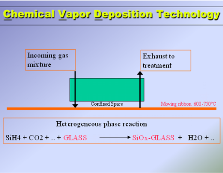

CVD Online Coating
What is CVD?
Chemical Vapor Deposition (CVD) is an on-line pyrolytic coating technology integrated directly into the float glass manufacturing process. A variety of techniques are available to deposit thin films on flat glass. The most widely used for producing high quality functional coatings can be subdivided into two classes:
-
physical vapour deposition (PVD)
-
chemical vapour deposition (CVD).
PVD processes include several options, sputtering being most widely used for glass. Sputtered coatings are generally referred to as soft coated. Pyrolytic coatings are applied using CVD methods and are often referred to as hard coated. Both types of coating offer their own advantages and disadvantages.
The advantages of CVD include a high deposition rate and high degree of control. Tuning the process is simply a matter of manipulating the vapor flows in the coating zone. And, because the coating is bonded to the glass surface, the result is a glass coating with unparalleled durability.
Depending on the desired end product, one or several coatings can be applied. Coatings can be applied inside the tin bath, at the lehr entry or both
How can we help?
We can provide comprehensive solutions, engineering, equipment design and supply and consulting services. Depending on the customers requirement, we can provide the following range of CVD applications :
-
CVD for reflective glass
-
CVD for low E applications
-
CVD for Solar applications
-
FGC Group LLC - Consulting & Engineering Products CVD Online Coating.mht


A glass melting Furnace is constantly subjected to different types of erosions and other problems during its campaign, which often lead in major Furnace damages. Cold repairs, apart from being costly, are also associated with large non production periods. Hot Repair solutions are preferred to extend the Furnace life without interrupting the production.
Beginning of 2008, Hotwork International established a Hot Repair Department for the Glass Industry providing also Ceramic Welding solutions. Ceramic Welding can be used for preventive maintenance or in case of emergency refractory repairs
Principle of Ceramic Welding
-
A mixture of ceramic and metallic particles are driven by oxygen flow and projected on to the hot Refractory Surface which requires the Repair.
-
The exothermic Reaction at the point of impact melts the projected powder and the Refractory Surface, creating a bond very similar to the effect of metallic welding.
-
It results in a fusion, bound to the Refractory.
-
Gaps and holes are filled up with the Ceramic Welding powder until the original state.
-
The Ceramic Welding is operated from the furnace outside with long welding lances.
-
These welding lances are custom made in our workshops to fit any requirement.
-
The nozzle of the lance can be angled in order to reach any position and to weld in to any direction.
-
During the operation of Ceramic Welding our crew can look inside the furnace directly or if required via Camera Lanes or through endoscopes.
-
All equipment, material, lances, machines are maintained in our workshops and pre tested to any operation by our high quality standards
Hot Repairs and Ceramic Welding are available for
Furnaces
-
AZS
-
Silica
-
Mulite
-
Alumina
-
…
If required a special Cleaning Lance is available to clean damaged spots before welding takes place. This enables the welding powder to fuse on a clean surface better than on the damaged refractory. These lances can also create Anchor points , increasing the stability of the welded section.
http://www.hotwork.ag/typo/hotwork/glass-industry/hot-repair-ceramic-welding.html
Brussels, inaugurated the world's largest flat glass production line in Klin, in the Moscow region, on Sept. 23, according to a release. The €150 million investment is AGC's fourth float line in Russia and the second at this plant. The unit has a capacity of 1,000 tons/day, and will serve the growing demand for construction glass.
The line, which started up on May 24, produces high-quality glass in thicknesses ranging from 4 millimeters to 12 mm for subsequent incorporation into super-insulating glasses, laminated safety glasses and decorative glasses (mirrors and varnished glasses) at the Klin plant. Part of the plant's float glass output is sold as is -- via the AGC Glass Russia distribution network -- in the form of large sheets for processors.
"This new line is not only ideally situated but also enables us to step up the local presence of our products and services in the large consumer centers of Saint Petersburg and Moscow," said Vladimir Shigaev, general manager, AGC Glass Russia, in the release. "The timing is perfect now that demand on the Russian market is rising, especially for high value-added products for the construction sector."
Technical innovations deployed in this new facility also mean more efficient float glass production in terms of both quality and energy consumption. These innovations make it possible to quickly adjust supply in line with demand, representing a real competitive edge on the Russian market, the release states.
"In addition to bolstering our glass industry leadership in Eastern Europe, this investment in Russia's largest glassmaking facility clearly illustrates AGC Glass Europe's ambition to shape the future of glass with innovative solutions," said Jean-François Heris, president and CEO, AGC Glass Europe.
AGC Glass Russia has the following facilities:
-
Klin (Moscow region): two float lines, and processing units for super-insulating glass, laminated glass, mirrors and varnished glass for use in the construction sector;
-
Bor (Nizhny Novgorod region): two float lines, production of tempered glass and laminated automotive glass and an AVO (Added Value Operations or any operation adding functionality to the basic glass, such as fittings, rain sensors, antennas, etc.) unit
-
Saint Petersburg: AVO unit
-
National construction glass distribution network
-
Automotive replacement glass network (five distribution centers and 17 installation centers).


|
fused_cast@technologist.com, owned and directed by Dr. P. Carlo Ratto is summarizing well over 35 years of experience in the technology, R&D, manufacturing, marketing and Customer support areas for fused cast refractory:
|
| |
|
|
|
http://www.fusedcast.com/experience.html
![]()
Good quality clear float glass
Thickness: 2mm-15mm
Common Size: 2000*1500mm, 1830*1220mm, 1830*2440mm, 2200*1650mm, 2100*1650mm, 2140x3050mm, 2140*3300mm, 2140*3660mm, 2250*3300mm, , , 2440*3660mm etc.
Used for architecture and deep processing.
| HS Code: | 70052900 |
|---|---|
| Trademark: | Farun, Huarun |
| Standard: | GB11614-1999 |
| Productivity: | 1,300 Tons/Day |
| Company: | Jiangmen Farun Glass Co., Ltd |
http://www.made-in-china.com/showroom/jmfarun/companyinfo/Jiangmen-Farun-Glass-Co-Ltd-.html
| Company: | Jiangmen Farun Glass Co., Ltd |
|---|
.: Weblog Themes By Pichak :.