نمودار عملكرد هر كمپرسور ( Compressor Map ) توسط شركت سازنده تهيه مي گردد . اين نمودار از دو محور افقي و عمودي و همچنين يك دسته منحني تشكيل شده كه محور افقي ميزان فلو (ظرفيت) و محور عمودي، هد (head ) يا فشار را نشان مي دهد . دسته منحني نيز بيانگر عملكرد كمپرسور در دورهاي مختلف مي باشد . در اين نمودار براي هر دوري يك نقطه حداقل و يك نقطه حداكثر ظرفيت (فلو) وجود دارد كه بين اين دو نقطه ، كاركرد كمپرسور، پايدار و قابل پيش بيني مي باشد . به نقطه حداكثر ظرفيت ، نقطه Stonewall و به نقطه حداقل ظرفيت، نقطه Surge گفته ميشود .
با اتصال نقاط سرج در دورهاي مختلف خط حد سرج بدست مي آيد . اگر كمپرسور در سمت راست اين خط كاركند در حالت پايدار و اگر در سمت چپ اين خط كار كند در حالت ناپايدار يا سرج مي باشد . سرج بصورت يك ناپايداري در فلو كه اساسا در كمپرسورهاي ديناميكي اتفاق مي افتد تعريف مي شود . اين پديده هنگامي اتفاق مي افتد كه كمپرسور قادر به توليد هد كافي براي غلبه بر مقاومت پايين دست خود نمي باشد و يا بطور ساده تر فشار ديسشارژ توليدي توسط كمپرسور كمتر از فشار پايين - دست آن است . در اين حالت ، يك حركت رفت و برگشتي (سيكلي) در جريان گاز ايجاد خواهد شد . علت اين جريان رفت و برگشتي كه به سيكل سرج معروف است در قسمت بعد توضيح داده شده است .
سيكل سرج
در شکل 9-1 ، سيكل سرج روي منحني مشخصه كمپرسور رسم شده است . فرض شود كمپرسور در نقطه پايدار D كار مي كند . با كاهش تقاضاي گاز در پايين دست كمپرسور، نقطه كار به سمت نقطه A (حد سرج) خواهد رفت و با گذشتن نقطه كار از A كمپرسور، ديگر توانايي افزايش فشار ديسشارژ را نخواهد داشت در نتيجه فشار ديسشارژ ، كمتر از فشار پايين دست خواهد شد كه اين سبب مي شود جهت فلو از طريق كمپرسور عكس شده و نقطه كار به B جهش پيدا كند . نقطه B ، نقطه پايداري در كاركرد كمپرسور نمي باشد .
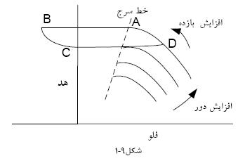
هنگامي كه فلو معكوس اتفاق مي افتد فشار پايين دست از طريق كمپرسور افت پيدا كرده و همزمان، فلو به سمت مثبت شدن خواهد رفت تا اينكه نقطه كار به C برسد . در نقطه C ميزان فلو به اندازه اي نيست كه بتواند فشار مورد نياز براي بازگشت به نقطه A را بسازد . در نتيجه نقطه كار به نقطه D ، يعني جايي كه ميزان فلو بيشتر از حدي است كه ب ار تقاضا دارد مي رود لذا در خروجي دوباره فشار ساخته مي شود تا اينكه به نقطه A برسد . اگر تغييري در شرايط كمپرسور ايجاد نشود اين عمل بصورت سيكلي تكرار خواهد شد .
پديده سرج مي تواند بوسيله كمبود فلوي ورودي نيز ايجاد شود زيرا كمبود فلوي ورودي نيز باعث كاهش فلوي خروجي مي شود . از آنجايي كه اين سيكل ممكن است چندين بار در ثانيه اتفاق بيفتد در نتيجه، نوسانات فشاري كه ايجاد مي كند بسيار آسيب زننده است . لذا براي جلوگيري از اين آسيب ها لازم است عواملي كه باعث نزديكي نقطه كار كمپرسور به خط سرج مي شوند شناخته شوند .
در بررسي اين عوامل از معادله هد پلي تروپيك و منحني مشخصه كمپرسور استفاده مي شود كه براي درك آن در قسمت بعد، مختصري درباره تراكم گاز طبيعي گفته شده است .
عوامل سرج
1. بالا بودن فشار در هدر خروجي در زمان به خط زدن يك كمپرسور .
2. كاهش فلوي كمپرسور به هر علت (كاهش مصرف در پايين دست يا بسته شد ن شيرهاي بين راهي خطوط انتقال يا تريپ خوردن ايستگاههاي بعدي)
3. افزايش فشار در هدر خروجي كمپرسور به علت بسته شدن مسير در پايين دست .
4. كاهش فشار گاز ورودي به كمپرسور به هر علت .
5. تغييرات در جرم مولكولي سيال به علت تغيير در تركيب گاز .
6. كاهش سريع دور به هر علت (مثلا توقف اضطراري)
با دقت در عوامل فوق الذكر نتيجه گرفته مي شود كه كمپرسور در هر يك از سه حالت كاري خود از قبيل راه اندازي ، شرايط عادي بهره برداري و يا زمان توقف اضطراري با خطر سرج مواجه است لذا سيستم كنترل بايد براي جلوگيري از سرج در هر يك از شرايط فوق، طراحي خاص آن شرايط را داشته باشد .
مشخصه هاي سرج
وقوع سرج در كمپرسورهاي سانتريفيوژ اغلب با مشخصه هايي همراه مي باشد كه در زير به آنها اشاره شده است:
1- معكوس شدن سريع فلوي خروجي كمپرسور در حد ميلي ثانيه (شکل 10-1)
2- نوسانات شديد فشار(شکل 10-1)
3- افزايش سريع دماي گاز عبوري و همچنين دماي داخلي كمپرسور به اين علت كه در طي پديده سرج ، گاز يكساني چندين بار در ثانيه از ديسشارژ كمپرسور عبور داده مي شود . (شکل 10-1)
4- ارتعاشات بيش از حد كمپرسوركه مي تواند سبب تريپ كمپرسور هم بشود.
5- سرو صدا و نويز زياد.
پدیده سرج
پدیده سرج به پدیده ای گفته می شود که در طول آن ، جهت جریان گاز در داخل کمپرسور برای لحظاتی برعکس می شود. یعنی گاز داخل کمپرسور ضمن غلبه بر نیروی پروانه، به طور معکوس به سمت ورودی کمپرسور حرکت می کند.
سرج در كمپرسورهای سانتريفوژ زمانی اتفاق می افتد كه جريان گاز ورودی به كمپرسور، كمتر از مقدار طراحی شده باشد. در اين حالت جريان ورودی يا فشار مکش از حد مجاز طراحی کمتر شده، گاز قادر به خروج از كمپرسور نبوده و کمپرسوردچار ارتعاشات شديدی می گردد. ارتعاشات ايجاد شده ممكن است باعث ايجاد خسارات زيادی به ساختمان كمپرسور، سروصدای زياد، تلف شدن ا نرژی و كاهش بازده کمپرسور شود.
دليل به وجود آمدن ارتعاشات، اين است که شفت کمپرسور از يک طرف در جهت دوران محرک چرخيده و از طرف ديگر به علت افزايش نسبت تراکم از حد مجاز، تحت نيرويی برای چرخش در خلاف جهت محرک قرار دارد. پديده سرج معمولا وقتی رخ می دهد که جريان بين 70%-50% زير مقدار طراحی باشد.
برای مشخص کردن پديده سرج تجهيزات خيلی پيچيده مورد نياز نمی باشد. ارتعاشات ايجاد شده معمولا به راحتی شنيده می شود و حتی با ايستادن در نزديكی كمپرسور احساس می شوند.
سیستم کنترل آنتی سرج
کـنـتـرل ســرج - لازم است که همه سیستم های کنترلی کمپرسور سانتریفوژ، مجهز به سیستمی برای کنترل و محافظت کمپرسور از پدیده سرج شده و مانع رسیدن شرایط عملکرد به محدوده سرج شوند.
روش های کنترل سرج عبارتند از:
1. استفاده از شیر تخلیه
هنگامی که به هر دلیلی فشار خروجی افزایش بیش از حدی داشته باشد، نسبت تراکم افزایش یافته و جریان ورودی کاهش می یابد و به حالت سرج نزدیک می شویم. در این حالت قبل از رسیدن به خط کنترل سرج، شیر تخلیه به طور اتوماتیک باز شده و جریان گاز به هوا تخلیه می شود. به محض تخلیه گاز، فشار خروجی کمتر شده، نسبت تراکم کاهش، و در نتیجه جریان گاز افزایش می یابد. افزایش جریان گاز، باعث دور شدن از شرایط سرج در کمپرسور می شود. در این روش گاز خروجی مستقیما وارد هوای آزاد می شود. بنابراین از این سیستم تنها در مواردی استفاده می شود که گاز ، خطرناک و یا قیمتی نباشد.
2. استفاده از لوله های برگشت جریان
اگر گاز خطرناک و یا باارزش باشد، از سیستم لوله های برگشت جریان استفاده می شود. بدین ترتیب که گازی که تخلیه می شود، دیگر وارد محیط آزاد نشده و دوباره وارد کمپرسور می گردد. چون درجه حرارت گاز در هنگام تراکم بالا می رود، اگر گاز برگشتی از لوله خروجی به لوله ورودی متصل شود، درجه حرارت گاز ورودی را افزایش می دهد که این باعث کاهش راندمان کمپرسور می شود. لذا لوله برگشت جریان باید بعد از خنک کننده نصب شود تا گاز خنک به ورودی کمپرسور بازگردانده شود. شیر برگشت جریان مانند شیر تخلیه می تواند به صورت اتوماتیک عمل کند.
سیستم کنترل سرج
سیستم کنترل سرج، یکی از سیستم هاي بسیار ضروري براي حفاظت کمپرسورهاي سانتریفیوژ می باشد سیستم کنترل سرج همیشه در وضعیت خودکار قرار دارد و به طور دستی در اختیار اپراتور نیست. اگر بنابه هر دلیل از جمله کمتر شدن شدت جریان ورودی از حداقل مقدار طراحی، نقص در سیستم ابزار دقیق و عدم عملکرد صحیح، سیستم کنترل خودکار سرج به درستی عمل نکند بایستی اپراتور خیلی سریع کمپرسور را از سرویس خارج کرده و بدین وسیله از بروز خسارت و صدمات جبران ناپذیر به کمپرسور و تجهیزات آن جلوگیری کند.
اهميت سيستمهاي كنترل سرج
از آنجايي كه كمپرسورهاي سانتريفيوژ، اجزاي گران و اصلي اكثر فرايند ها هستند حفاظت از اين دارائي پرارزش از آسيبهايي كه به سبب سرج اتفاق مي افتد بسيار ضروريست . اين وظيفه بر عهده سيستمي به نام سيستم كنترل سرج (يا آنتي سرج) مي باشد .
البته به اين نكته توجه شود كه بهتر است بهره بردار، نقطه كار كمپرسور را مد نظر داشته باشد و اجازه ندهد نقطه كار به خط سرج نزديك شود ، به طوري كه لازم باشد سيستم كنترلي عمل كند زيرا اين احتمال هر چند ضعيف را بايد داد كه سيستم كنترلي ممكن است بر اثر مشكلي نتواند درست عمل كند .
اندازه گيري در سيستمهاي كنترل سرج
سرج پديده ايست كه خيلي سريع اتفاق مي افتد بنابراين براي داشتن يك كنترل مناسب روي اين پديده، فقط توجه به انتخاب شير آنتي سرج مناسب، يا داشتن يك الگوريتم كنترلي مناسب و يا استفاده از يك كنترلر اختصاصي؛ كافي نمي باشد، بلكه بايد توجه خاصي نيز به ابزارهاي اندازه گيري در پروسه شود . زيرا اين ابزارها هستند كه نقطه كار كمپرسور را مشخص مي كنند . اندازه گيريهاي كليدي در سيستم كنترل سرج، شامل اندازه گيري ميزان فلو گاز عبوري از كمپرسور، فشار ساكشن و ديسشارژ و همچنين دماي گاز ميباشند كه توسط ترانسميترها صورت مي گيرند . ترانسميترها در حقيقت وسايلي هستند كه خروجي سنسورها يا مبدلها (ترانسديوسرها ) را گرفته و به يك سيگنال با سطح مناسب براي اعمال به ورودي كنترلرها تبديل مي كنند . امروزه معمولا هر دو قسمت ترانسديوسر و ترانسميتر در يك مجموعه قرار دارند و كل اين مجموعه تحت نام ترانسميتر شناخته مي شود . در اينجا و در مباحث بعدي نيز منظور از كلمه ترانسميتر، مجموعه ترانسميتر و ترانسديوسر مي باشد . انتخاب و كاليبراسيون صحيح ترانسميترها از لحاظ مواردي همچون پاسخ زماني ، درستي و همچنين عدم قطعيت اندازه گيري ، مستقيما در درجه دقت سيستم كنترل سرج و ميزان قابليت آن در آشكارسازي سرج تاثيرگذار است .
كنترلرها ي سرج
همانطور كه گفته شد سيستم كنترل سرج، يكي از سيستمهاي ضروري براي كمپرسور سانتريفيوژ مي باشد كه وظيفه دارد آن را از رفتن به سرج محافظت كند . امروزه سيستمهاي كنترل سرج به صورتهاي مختلفي بكار گرفته شوند اما همه آنها در يك هدف اوليه كه پيش بيني و جلوگيري از وقوع سرج مي باشد مشتركند . سيستمهاي كنترل بايد فلو عبوري و هد (head ) كمپرسور را اندازه گرفته و از آن، نقطه كار كمپرسور را بدست آورند . آنگاه در صورتي كه فلو عبوري از كمپرسور در يك هد معين، كمتر از يك ميزان فلو حداقل گرديد بايد شير آنتي سرج در يك زمان مشخص و در يك ست پوينت خاصي كه سيستم كنترل سرج براي آن معين مي كند باز شود . با باز شدن اين شير، فلو بيشتري براي كمپرسور مهيا شده و هد كمپرسور نيز كاهش خواهد يافت .
پياده سازي سخت افزاري كنترل كننده هاي سرج
دو روش براي پياده سازي الگوريتمهاي كنترل سرج وجود دارد :
1- استفاده از سيستمهاي بر پايه PLC : در اين روش الگوريتم كنترل سرج همانند قسمتي از يك برنامه در داخل PLC قرار گرفته بدون اينكه نياز به سخت افزار خاصي باشد
2- استفاده از يك كنترلر مستقل : اين روش براي آن كاربردهايي كه PLC ، توانايي مهيا كردن كنترل سرج مناسب را ندارد كاربرد دارد . در هر صورت، چه از PLC و چه از كنترلر اختصاصي استفاده شود كنترلر بايد سريع باشد و بتواند در فواصل كوتاه ورودي ها را بخواند .
برچسبها: بررسي پديده سرج در كمپرسورها و رفع اين مشكل توسط آ

A new oxy-fuel glass melting technology can help glassmakers increase
their furnace capacity, improve glass quality and/or redistribute
furnace energy more effectively.

Recently,
however, a new system* was developed that overcomes these limitations.
Rather than firing horizontally, the system directs the oxy-fuel flames
almost vertically down onto the batch surface at the charging end of
the furnace. By modifying conventional oxy-fuel melting technology, the
new melting system provides significant improvements in melting rates
and/or quality.

Heat Transfer in Glass Melting
Efficient heat transfer from the heat source to the batch is crucial in glass production. Total heat transfer can basically be described as the sum of the radiative and convective heat transfers, as shown in the equation:QT = QR + QC
where QT is the total heat transfer to the batch, QR is the radiative heat transfer and QC is the convective heat transfer.
Both
radiant (first term) and convective (second term) heat transfer depend
on well-known heat transfer variables, such as the simplified equation
shown in Equation 1, where Q is the heat to the surface (in watts), e
is the emissivity, f is the radiation function, s is the
Stefan-Boltzmann constant, g is the convection function, hc is the
convection coefficient, A is the area of the batch/glass surface under
consideration, Ts is the absolute temperature of the radiant source, Tg
is the absolute temperature of the gases and Tb is the absolute
temperature of the batch.

In conventional furnaces, the presence of relatively thick boundary layers and a low thermal driving force dictate that approximately 95% of the total heat transfer to the batch and glass bath comes from the combined radiation from the flame and superstructure. Therefore, the attainable heat transfer in conventional furnaces is a function of the melter area and the maximum temperature limit of the superstructure refractory. Since refractory materials have fixed maximum temperatures before failure, the only way to improve the radiative melting rate in fossil fuel glass furnaces is to increase the batch surface area. As a result, existing furnace technology constrains the unit melting rate of furnaces within a well-established range.
Conventional oxy-fuel
firing can enhance radiative heat transfer, but its impact on
convective transfer is small. Higher flame temperatures and the
enhanced emissivity of the combustion products increase the radiation
directly from the combustion space, but low velocities, thick boundary
layers and the relatively low temperature of combustion products in
contact with the batch and glass bath (compared to the temperature of
the flame itself) diminish the impact on the convective component.

Oxy-fuel flames contain significant concentrations of partially reacted and partially dissociated species. As these species move toward the cool batch surface, they oxidize/recombine and liberate still more energy to the surface, further enhancing the convective heat transfer. This process also increases radiative flux because the burners in the new melting system are designed to produce the majority of the high-temperature combustion reactions near the batch, thereby increasing the radiation to the batch.
The increase in total
heat transfer to the batch enables increased melting rates. Further,
since the burners are installed in the crown rather than the side
walls, fewer obstructions affect burner placement. Consequently, the
new melting system can supply more energy per square foot of batch
surface area without increasing refractory temperatures beyond normal
operating limits. The result is a melting system that enables furnaces
to melt more glass, and/or higher quality glass, in a furnace of a
given size.
Proving the New Technology
Owens Corning’s Composites group provided the first opportunity to demonstrate this new technology in a production furnace. In 1996, BOC and Owens Corning converted an oxy-fuel furnace to the new melting technology without interrupting production. During a four-month trial, the furnace produced glass at significantly higher capacity than could be achieved using horizontal-fired oxy-fuel burners alone. This study demonstrated:- A pull rate increase greater than 50% over conventional oxy-fuel capacity
- No increase in emissions on a per ton basis
- No change in analyzed glass chemistry
- No observable damage to the melter superstructure
- A reduction in glass defects

Refining the Technology
The results of the Owens Corning collaboration supported the expectation that the new vertical melting system was commercially viable. To understand the relative contributions of convective and radiant heat transfer, BOC modeled the process with computational fluid dynamics (CFD). Of particular interest were the effects of flame shape, velocity and angles on the rate of heat transfer, the area of maximum heat transfer and batch carryover. Figure 3 illustrates how the heat transfer varies from the center of the flame and confirms that the total heat transfer is significantly higher than the radiant transfer provided by conventional melting technology. The green line represents the CFD calculation of heat transfer (primarily through radiation) to the batch from the background source—i.e. the furnace structure. The red line represents the CFD calculation of heat transfer to the batch directly from the flame. The direct flame heat transfer carries a large convective component, and it decays rapidly with distance from the axis of impingement. The blue line is the total heat transfer to the batch predicted by CFD—the sum of background and direct flame transfer.To verify the implications of the CFD modeling, BOC teamed with Maxon Corp. to design and build a well-instrumented vertically firing test furnace at Maxon’s facility in Muncie, Ind. The furnace incorporated a vertically adjustable firing target to simulate the varying crown-to-batch distances found in real-world glass furnaces.
Trial
firings of burners in the test furnace validated the CFD model
predictions. As Figure 3 illustrates, a very good correlation was
obtained between the direct flame heat transfer predicted by CFD (red
line) and the direct flame heat transfer measured in the test furnace
(black squares). The test furnace data also helped to optimize burner
design and flow characteristics for installing the system in crowns of
various heights.
Commercial Demonstrations
Increased Production of Soda-Lime-Silica Glass. The first trials on soda-lime-silica glass took place in mid-1998 in a three-port air-fuel tableware furnace. The furnace’s designed pull and actual maximum pull were 60 tons per day (TPD). Attempts to increase this pull rate with port firing resulted in unacceptable deterioration in glass quality.The objectives of this trial were to determine the maximum pull rate attainable by the new melting technology with equivalent or better quality and color control; the ability and success of converting a regenerative furnace “on the fly” to 100% oxy-fuel and vertical melting; and the effect of the new melting technology on glass chemistry (if any).
This installation also provided the opportunity to demonstrate the operational flexibility of the new technology by using it both as a stand-alone melting technology (full conversion) and as a boost to the regenerative furnace. BOC engineers converted the furnace in stages from air-fuel to 100% with the new technology and ultimately back to air fuel—all without interrupting production.
Key observations from this trial included:
- Increased production to 85 TPD with no deterioration in glass quality or color
- No evidence of batch carryover from the vertical flames
- No change in glass chemistry
- Excellent color control
- More stable furnace operation
Melting Boost in a Large Regenerative Furnace. Later that same year, the capability of the new melting technology was demonstrated in a large regenerative furnace—a four-port, 750-square-foot flint container furnace equipped with approximately 1000 kw of electric boost. The plant’s management wanted to pull the furnace as hard as their forming capacity would allow, but attempts to increase pull resulted in glass temperatures at the throat that were too high for the forehearth to condition. Further increases in pull also resulted in unacceptable levels of batch stones. Therefore, the furnace was limited to pulling a tonnage equivalent to 82.5% of forming capacity.
The plant secured a 30-day variance from the production limits imposed by its environmental permit and installed the new technology. Port number one of the furnace was blocked off, and the vertical burners were installed in the port one region of the crown. At the end of the demonstration, the vertical burners were removed, and port one was returned to air fuel operation. Production was never interrupted.
The goals of this installation were to operate the new technology while reducing electric boost to achieve:
- A sustained pull rate up to full capacity of the forming line
- A throat temperature reduction
- Elimination of batch stones
In
addition to operating at higher pull and reduced electric boost levels,
the hotspot temperature was reduced by an amount that would equate to
another 10.5% increase in pull for a furnace of this size. Had the
forming equipment been able to handle the load, the fuel in the new
technology could have been increased to achieve a pull increase of
approximately 30%. (Other potential applications of the new melting
technology are discussed in the sidebar below.)
Observations in Operating Furnaces
The new technology can also inject
a disproportionate amount of energy into the charging end through
crown-mounted burners. This redistribution of energy increases the
temperature of the charging end, reducing the temperature differential
between the charging end and the hot spot. Conventional wisdom suggests
that reducing this differential below the range of 150-200 degrees F
(depending on the industry segment) would short-circuit the furnace
convection currents. However, no observable negative change in
convection currents or in the basic operation of the melter occurs with
the new technology.
Enhanced Profitability
By providing
glassmakers with a wide range of flexibility, the new system represents
not only a revolution in glass melting technology, but also a promise
of enhanced glass industry profitability.
Editor's Note
For More Information
SIDEBAR: Capabilities of the New Melting Technology
Complete Conversions: Full CGM Furnaces
A “full CGM furnace” is an oxy-fuel furnace that incorporates vertical
CGM burners in the charging end and horizontal oxy-fuel burners in the
refining end. These installations are characterized by a high melting
rate (T/ft2) and excellent fuel efficiency. Test data suggests that, as
a rule, CGM provides capacity improvements of at least 25% over
air-fuel and conventional oxy-fuel furnaces.
A greenfield (new) furnace designed for CGM operation offers glassmakers significant benefits, including:
- Capital reduction from elimination of regenerators and recuperators
- Capital reduction from smaller furnace footprint
- Capital and operating cost reduction from elimination of electric boost system
- Fuel reduction per ton with little to no efficiency decay over the life of the furnace
- Reduction of NOx emissions
CGM Hybrid Furnaces
The
hybrid design is of specific interest to the float glass industry. As
its name implies, a hybrid furnace is a mixed design. The area of the
first two or three ports looks like a CGM furnace; there are no
air-fuel burners and no regenerators. The firing is provided by CGM
burners in the crown. The remainder of the furnace looks like a
standard regenerative float furnace, with conventional air-fuel
burners, waist and working end. In this furnace, virtually all of the
melting is done by the CGM burners, while the air-fuel zone provides
refining capacity. This design provides many of the advantages of CGM
firing, and it requires only 40-60% as much oxygen as a standard
oxy-fuel furnace. Such a design offers float glass makers the following
benefits in comparison to standard regenerative design:
- Reduced capital cost from the partial elimination of the regenerator packs
- Reduced batch carryover and reduced airflow demand through remaining regenerators (i.e., potential for furnace life extension)
- Reduced NOx emissions
- Greater capacity in the same furnace footprint
A CGM-boosted furnace is an air-fuel furnace in which CGM burners have been installed in the crown at the charging end. The number of CGM burners and the amount of fuel injected through them can vary widely, depending on furnace size and the amount of boost required. In some cases, the first one or several ports may be blocked off, with the fuel flowing instead through crown-mounted CGM burners in the affected port areas. In other cases, it will not be necessary to shut off any of the ports, but only to supplement them with CGM firing.
Though specific cases will differ, it is generally possible to use CGM to increase the capacity of an air fuel furnace by at least 25%. On furnaces in good working order, this may be taken as an increase above rated air-fuel capacity to achieve significant revenue increases with limited incremental cost.
Furnaces that
have developed pull constraints (e.g., plugged checkers, deteriorating
ports or port walls, hot spot refractory deterioration) are
particularly attractive candidates for CGM boosting. The enhanced
thermal efficiency of the CGM flames and the reduction of air-fuel
relieve the strain on regenerator air-flow, extending regenerator life.
Reduction of electric boosting also slows the process of sidewall wear.
Through these mechanisms, CGM boosting not only recovers or increases
the capacity of an air fuel furnace, but can extend the life of its
campaign. More importantly, CGM can increase the tonnage (cumulative
tons/square foot of melter area) melted over the furnace campaign.
SIDEBAR: Success at Owens Corning
“We replaced the eight existing horizontal burners with two vertical CGM burners and immediately began seeing results,” Baker said. “The furnace was easier to control because of the small number of burners and the sensitivity of the technology, and its faster melting speed enabled us to increase our throughput by 25%. But most importantly, the CGM lowered our emissions and increased our performance capabilities. Our particulate emissions have been reduced by 75%, while our NOx emissions have dropped by 80-90%, and we’re achieving better quality glass with the new system.”
Since the initial installation, Owens Corning has also begun using the CGM technology in four additional facilities, and it plans to install the technology in additional plants in the future. “It’s been a very good collaboration,” Baker said.
 | Control Station with Flow meter for Heavy Oil and Compressed air – station without isolation before start up. |
 | Control Station for Heavy Oil and Compressed air with preheating unit installed at an operating furnace. |
 | Control Station for Heavy Oil at a Recuperative Furnace. |
 | Control Station for incoming Supply for Heavy Oil. |
 | Heavy Oil preheater |
 | Control Station for Natural Gas for a Float Glass Line 600 T/P |
 | Control Station for Natural Gas for a Container Glass Furnace – compact Version. |
 | Flow Meter Station for Natural Gas for a Container Glass Furnace |
 | Assembly of Control and Flow Meter Station at a Container Glass Furnace |
ادامه مطلب
احتراق و سوخت ها براي كوره هاي شيشه
http://www.4shared.com/office/LY2nVJ5J/COMBUSTION__FUELS_FOR_GLASS_FU.html
برچسبها: احتراق و سوخت ها براي كوره هاي شيشه
.: Weblog Themes By Pichak :.