
شیشه محافظ اشعه ایکس ( شیشه ضد اشعه ایکس) دیدی واضح فراهم می سازد در حالیکه در مقابل اشعه گاما و اشعه ایکس محافظ می کند.
22 تا 65 درصد وزن شیشه محافظ اشعه ایکس عموما مربوط به اکسید سرب می شود و شیشه به دلیل وضوح بالا، جایگزین مناسبی برای سایر مواد محافظ اشعه ایکس می باشد. بخصوص اینکه شیشه مقاومت بیشتری از پلاستیک در مقابل خراشیدگی دارد.
شیشه محافظ اشعه ایکس تنها برای یک منظور طراحی و تولید شده است و آن تهیه ماده ای با کیفیت با شفافیت بالا جهت محافظت در مقابل اشعه ایکس می باشد. سرب و باریم موجود در این شیشه سبب محافظت از V100 تا kV300 می شود. از این رو این محصول در تمامی کاربردهای پزشکی،تکنیکی و یا تحقیقاتی قابل اعتماد می باشد.

کاربردها:
-پنجره نمایش اتاق سی تی اسکن و اشعه ایکس
-صفحه تشخیص پزشکی
-صفحه محافظ در آزمایشگاه ها
-لنز محافظ عینک های ایمنی
برچسبها: شیشه محافظ اشعه ایکس
Sputtering is carried out in vacuum conditions. It is not only able to provide highly uniform thin-film coatings of high quality, but these films can also be built up in multiple layers. From transparent conductive films on glass substrates, through energy-efficient architectural and automotive glass coatings, to antireflective treatments that reduce glare, sputtering is applied to the products for a wide range of industrial applications.
برچسبها: Sputtering deposition
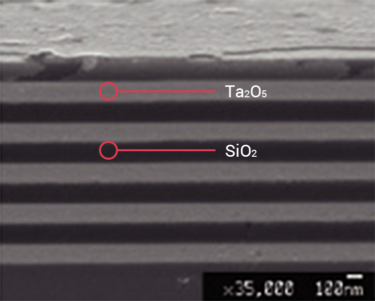
Desired optical properties can be achieved by coating the substrate with multilayer films with the thickness close to the wavelengths of visible light.
برچسبها: coating film
Anti-reflection (AR) film has been used in various industrial fields, and there has been constant demand for lower reflectance AR film with neutral reflectance color and anti-smudge property. Conventionally, these functions are achieved only though a dry coating method such as the sputtering coating method. Leveraging new film design and materials, AGC successfully added such high performance to AR film by using the wet coating method which is known as a promising low-cost coating method.
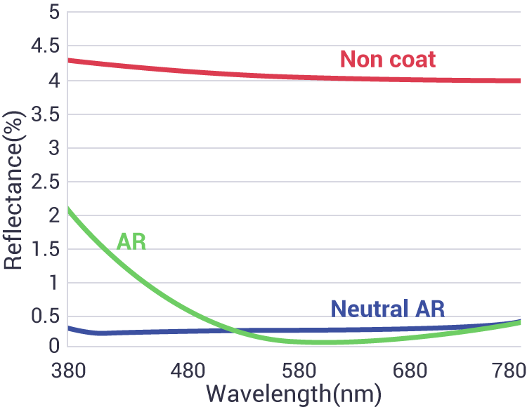
أNOn coat

AR

Neutral AR

برچسبها: شيشه ضد انعكاس
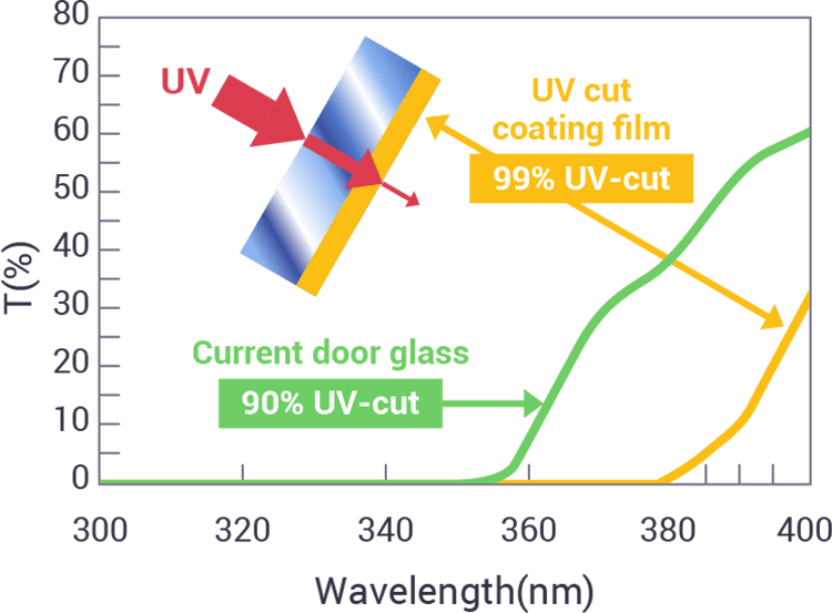
UV Verre Premium™ is a UV-blocking, tempered glass for automotive applications. It was created through the integration of AGC's materials technologies and wet coating methods, and has great durability and UV-blocking property as its surface is covered with AGC's robust hybrid materials. This product is our response to the demand among female drivers who want to avoid sunburn while driving. AGC aims to help create indoor-comfort for drivers.
Transmittance of UV-blocking glass
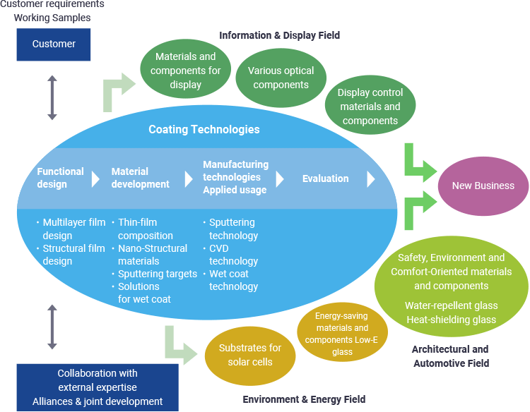
Coating processing adds new functions to glass, film resin and various other substrates.
برچسبها: كوتينگ شيشه
Antibacterial Glass Market size will grow from USD 160 million in 2015 to over USD 270 million in 2023, as reported by the latest study by Global Market Insights, Inc. Growing prevalence of nosocomial infections or Hospital Acquired Infections (HAIs) will drive the global antibacterial glass market over the next few years.
Growing popularity of antimicrobial/antifouling coatings coupled with technological innovation will drive industry demand on a global level. Silver, with more than USD 148 million in revenue for 2015, is expected to remain the preferred active ingredient due to its low toxicity to humans and antifouling nature.
Europe antibacterial glass market size, by application, 2012-2023 (USD Million)
Other active ingredients include powder coatings of materials such as copper, zeolite, silicon, and titanium. Copper is slowly becoming the material of choice and dominating the other powder coatings market to a large extent and is looked at a key substitute for silver.
Hospitals continued to dominate antibacterial glass market share in 2015, with more than USD 68 million in revenue; isolation rooms, burn units, hematology and oncology units are key application areas. Antibacterial glass provides an architectural solution to these ailments and can be used in furniture, partitions, and intensive care units among others. This segment is expected to grow significantly over the forecast time-scale. Companies looking to venture into the market have been targeting hospitals as the preferred end-use industry due to the high expected demand for antibacterial glass in this sector.
Flat glass used for antibacterial glass production is made from float glass, which requires silicon dioxide (sand), sodium carbonate (soda), calcium carbonate (limestone), and other additives. While AGC’s process involves infusion of silver ions into the glass, companies such as Nippon Sheet Glass (NSG) use a combination of coatings to reduce viral contamination.
Apart from high technology markets of the U.S. and the European Union, awareness levels in large consumer markets of China, India, Brazil and other developing countries is significantly lower. This has emerged as one of the key challenges for market participants in recent times.
There are high entry barriers to the industry, which can be attributed to infrastructure and capital investments needed for participants to manufacture on a commercial scale. Existing suppliers have been trying to establish themselves on a broader level, and have float tanks and production sites across the globe.
To access sample pages or view this report titled, “Antibacterial Glass Market Size By Application (Hospitals, Food & Beverage, Military Equipment, Household/Residential), By Active Ingredient (Silver), Industry Analysis Report, Regional Outlook, Application Potential, Price Trends, Competitive Market Share & Forecast, 2016 - 2023” in detail along with the table of contents, please click on the link below:
https://www.gminsights.com/industry-analysis/antibacterial-glass-market
Key insights from the report include:
- Global antibacterial glass market will grow at 6.9% CAGR, and looks poised to exceed USD 270 million by 2023.
- Silver antimicrobial glass is forecast to see revenue exceeding USD 253 million by 2023, which would be more than 93% of the global earnings at that time.
- Food & beverage applications will continue to be attractive, with growth forecast at 7.1% CAGR from 2016 to 2023. These products facilitate storage for a prolonged period of time by suppressing the propagation of bacteria and other microorganisms in glass containers. Besides being used for storage, these are also used in restaurants, canteens, food show cases.
- In military settings, where equipment needs to be kept sterile and sanitary despite volatile working conditions, antibacterial glass and coatings have been gaining importance. Electronics, automotive, construction, and personal care are among the emerging applications for this industry.
- Europe antibacterial glass market size was USD 97.5 million in 2015. The region is heavily regulated, with standards such as EN 13697, EN 1276, and EN 1650 in place to evaluate the bactericidal and fungicidal properties of chemical disinfectants used in the food industry.
- Global antibacterial glass market share is dominated by a few suppliers such as AGC Glass Europe, Saint-Gobain, Nippon Sheet Glass, etc. AGC is integrated across the value chain, and provides an end-to-end solution, from glass production to distribution.
Global Market Insights has segmented the antibacterial glass industry on the basis of ingredient, application and region:
- Antibacterial Glass Market Ingredient Analysis (Revenue, USD Million, 2012 - 2023)
- Silver
- Others
- Antibacterial Glass Market Application Analysis (Revenue, USD Million, 2012 - 2023)
- Hospitals
- Food and Beverage
- Military Equipment
- Household
- Others
- Antibacterial Glass Market Regional Analysis (Revenue, USD Million, 2012 - 2023)
- North America
- Europe
- Asia Pacific
- Latin America
- Middle East & Africa (MEA)
برچسبها: افزایش محبوبیت پوشش های ضد میکروبی برروي شيشه ها


A new oxy-fuel glass melting technology can help glassmakers increase
their furnace capacity, improve glass quality and/or redistribute
furnace energy more effectively.

Recently,
however, a new system* was developed that overcomes these limitations.
Rather than firing horizontally, the system directs the oxy-fuel flames
almost vertically down onto the batch surface at the charging end of
the furnace. By modifying conventional oxy-fuel melting technology, the
new melting system provides significant improvements in melting rates
and/or quality.

Heat Transfer in Glass Melting
Efficient heat transfer from the heat source to the batch is crucial in glass production. Total heat transfer can basically be described as the sum of the radiative and convective heat transfers, as shown in the equation:QT = QR + QC
where QT is the total heat transfer to the batch, QR is the radiative heat transfer and QC is the convective heat transfer.
Both
radiant (first term) and convective (second term) heat transfer depend
on well-known heat transfer variables, such as the simplified equation
shown in Equation 1, where Q is the heat to the surface (in watts), e
is the emissivity, f is the radiation function, s is the
Stefan-Boltzmann constant, g is the convection function, hc is the
convection coefficient, A is the area of the batch/glass surface under
consideration, Ts is the absolute temperature of the radiant source, Tg
is the absolute temperature of the gases and Tb is the absolute
temperature of the batch.

In conventional furnaces, the presence of relatively thick boundary layers and a low thermal driving force dictate that approximately 95% of the total heat transfer to the batch and glass bath comes from the combined radiation from the flame and superstructure. Therefore, the attainable heat transfer in conventional furnaces is a function of the melter area and the maximum temperature limit of the superstructure refractory. Since refractory materials have fixed maximum temperatures before failure, the only way to improve the radiative melting rate in fossil fuel glass furnaces is to increase the batch surface area. As a result, existing furnace technology constrains the unit melting rate of furnaces within a well-established range.
Conventional oxy-fuel
firing can enhance radiative heat transfer, but its impact on
convective transfer is small. Higher flame temperatures and the
enhanced emissivity of the combustion products increase the radiation
directly from the combustion space, but low velocities, thick boundary
layers and the relatively low temperature of combustion products in
contact with the batch and glass bath (compared to the temperature of
the flame itself) diminish the impact on the convective component.

Oxy-fuel flames contain significant concentrations of partially reacted and partially dissociated species. As these species move toward the cool batch surface, they oxidize/recombine and liberate still more energy to the surface, further enhancing the convective heat transfer. This process also increases radiative flux because the burners in the new melting system are designed to produce the majority of the high-temperature combustion reactions near the batch, thereby increasing the radiation to the batch.
The increase in total
heat transfer to the batch enables increased melting rates. Further,
since the burners are installed in the crown rather than the side
walls, fewer obstructions affect burner placement. Consequently, the
new melting system can supply more energy per square foot of batch
surface area without increasing refractory temperatures beyond normal
operating limits. The result is a melting system that enables furnaces
to melt more glass, and/or higher quality glass, in a furnace of a
given size.
Proving the New Technology
Owens Corning’s Composites group provided the first opportunity to demonstrate this new technology in a production furnace. In 1996, BOC and Owens Corning converted an oxy-fuel furnace to the new melting technology without interrupting production. During a four-month trial, the furnace produced glass at significantly higher capacity than could be achieved using horizontal-fired oxy-fuel burners alone. This study demonstrated:- A pull rate increase greater than 50% over conventional oxy-fuel capacity
- No increase in emissions on a per ton basis
- No change in analyzed glass chemistry
- No observable damage to the melter superstructure
- A reduction in glass defects

Refining the Technology
The results of the Owens Corning collaboration supported the expectation that the new vertical melting system was commercially viable. To understand the relative contributions of convective and radiant heat transfer, BOC modeled the process with computational fluid dynamics (CFD). Of particular interest were the effects of flame shape, velocity and angles on the rate of heat transfer, the area of maximum heat transfer and batch carryover. Figure 3 illustrates how the heat transfer varies from the center of the flame and confirms that the total heat transfer is significantly higher than the radiant transfer provided by conventional melting technology. The green line represents the CFD calculation of heat transfer (primarily through radiation) to the batch from the background source—i.e. the furnace structure. The red line represents the CFD calculation of heat transfer to the batch directly from the flame. The direct flame heat transfer carries a large convective component, and it decays rapidly with distance from the axis of impingement. The blue line is the total heat transfer to the batch predicted by CFD—the sum of background and direct flame transfer.To verify the implications of the CFD modeling, BOC teamed with Maxon Corp. to design and build a well-instrumented vertically firing test furnace at Maxon’s facility in Muncie, Ind. The furnace incorporated a vertically adjustable firing target to simulate the varying crown-to-batch distances found in real-world glass furnaces.
Trial
firings of burners in the test furnace validated the CFD model
predictions. As Figure 3 illustrates, a very good correlation was
obtained between the direct flame heat transfer predicted by CFD (red
line) and the direct flame heat transfer measured in the test furnace
(black squares). The test furnace data also helped to optimize burner
design and flow characteristics for installing the system in crowns of
various heights.
Commercial Demonstrations
Increased Production of Soda-Lime-Silica Glass. The first trials on soda-lime-silica glass took place in mid-1998 in a three-port air-fuel tableware furnace. The furnace’s designed pull and actual maximum pull were 60 tons per day (TPD). Attempts to increase this pull rate with port firing resulted in unacceptable deterioration in glass quality.The objectives of this trial were to determine the maximum pull rate attainable by the new melting technology with equivalent or better quality and color control; the ability and success of converting a regenerative furnace “on the fly” to 100% oxy-fuel and vertical melting; and the effect of the new melting technology on glass chemistry (if any).
This installation also provided the opportunity to demonstrate the operational flexibility of the new technology by using it both as a stand-alone melting technology (full conversion) and as a boost to the regenerative furnace. BOC engineers converted the furnace in stages from air-fuel to 100% with the new technology and ultimately back to air fuel—all without interrupting production.
Key observations from this trial included:
- Increased production to 85 TPD with no deterioration in glass quality or color
- No evidence of batch carryover from the vertical flames
- No change in glass chemistry
- Excellent color control
- More stable furnace operation
Melting Boost in a Large Regenerative Furnace. Later that same year, the capability of the new melting technology was demonstrated in a large regenerative furnace—a four-port, 750-square-foot flint container furnace equipped with approximately 1000 kw of electric boost. The plant’s management wanted to pull the furnace as hard as their forming capacity would allow, but attempts to increase pull resulted in glass temperatures at the throat that were too high for the forehearth to condition. Further increases in pull also resulted in unacceptable levels of batch stones. Therefore, the furnace was limited to pulling a tonnage equivalent to 82.5% of forming capacity.
The plant secured a 30-day variance from the production limits imposed by its environmental permit and installed the new technology. Port number one of the furnace was blocked off, and the vertical burners were installed in the port one region of the crown. At the end of the demonstration, the vertical burners were removed, and port one was returned to air fuel operation. Production was never interrupted.
The goals of this installation were to operate the new technology while reducing electric boost to achieve:
- A sustained pull rate up to full capacity of the forming line
- A throat temperature reduction
- Elimination of batch stones
In
addition to operating at higher pull and reduced electric boost levels,
the hotspot temperature was reduced by an amount that would equate to
another 10.5% increase in pull for a furnace of this size. Had the
forming equipment been able to handle the load, the fuel in the new
technology could have been increased to achieve a pull increase of
approximately 30%. (Other potential applications of the new melting
technology are discussed in the sidebar below.)
Observations in Operating Furnaces
The new technology can also inject
a disproportionate amount of energy into the charging end through
crown-mounted burners. This redistribution of energy increases the
temperature of the charging end, reducing the temperature differential
between the charging end and the hot spot. Conventional wisdom suggests
that reducing this differential below the range of 150-200 degrees F
(depending on the industry segment) would short-circuit the furnace
convection currents. However, no observable negative change in
convection currents or in the basic operation of the melter occurs with
the new technology.
Enhanced Profitability
By providing
glassmakers with a wide range of flexibility, the new system represents
not only a revolution in glass melting technology, but also a promise
of enhanced glass industry profitability.
Editor's Note
For More Information
SIDEBAR: Capabilities of the New Melting Technology
Complete Conversions: Full CGM Furnaces
A “full CGM furnace” is an oxy-fuel furnace that incorporates vertical
CGM burners in the charging end and horizontal oxy-fuel burners in the
refining end. These installations are characterized by a high melting
rate (T/ft2) and excellent fuel efficiency. Test data suggests that, as
a rule, CGM provides capacity improvements of at least 25% over
air-fuel and conventional oxy-fuel furnaces.
A greenfield (new) furnace designed for CGM operation offers glassmakers significant benefits, including:
- Capital reduction from elimination of regenerators and recuperators
- Capital reduction from smaller furnace footprint
- Capital and operating cost reduction from elimination of electric boost system
- Fuel reduction per ton with little to no efficiency decay over the life of the furnace
- Reduction of NOx emissions
CGM Hybrid Furnaces
The
hybrid design is of specific interest to the float glass industry. As
its name implies, a hybrid furnace is a mixed design. The area of the
first two or three ports looks like a CGM furnace; there are no
air-fuel burners and no regenerators. The firing is provided by CGM
burners in the crown. The remainder of the furnace looks like a
standard regenerative float furnace, with conventional air-fuel
burners, waist and working end. In this furnace, virtually all of the
melting is done by the CGM burners, while the air-fuel zone provides
refining capacity. This design provides many of the advantages of CGM
firing, and it requires only 40-60% as much oxygen as a standard
oxy-fuel furnace. Such a design offers float glass makers the following
benefits in comparison to standard regenerative design:
- Reduced capital cost from the partial elimination of the regenerator packs
- Reduced batch carryover and reduced airflow demand through remaining regenerators (i.e., potential for furnace life extension)
- Reduced NOx emissions
- Greater capacity in the same furnace footprint
A CGM-boosted furnace is an air-fuel furnace in which CGM burners have been installed in the crown at the charging end. The number of CGM burners and the amount of fuel injected through them can vary widely, depending on furnace size and the amount of boost required. In some cases, the first one or several ports may be blocked off, with the fuel flowing instead through crown-mounted CGM burners in the affected port areas. In other cases, it will not be necessary to shut off any of the ports, but only to supplement them with CGM firing.
Though specific cases will differ, it is generally possible to use CGM to increase the capacity of an air fuel furnace by at least 25%. On furnaces in good working order, this may be taken as an increase above rated air-fuel capacity to achieve significant revenue increases with limited incremental cost.
Furnaces that
have developed pull constraints (e.g., plugged checkers, deteriorating
ports or port walls, hot spot refractory deterioration) are
particularly attractive candidates for CGM boosting. The enhanced
thermal efficiency of the CGM flames and the reduction of air-fuel
relieve the strain on regenerator air-flow, extending regenerator life.
Reduction of electric boosting also slows the process of sidewall wear.
Through these mechanisms, CGM boosting not only recovers or increases
the capacity of an air fuel furnace, but can extend the life of its
campaign. More importantly, CGM can increase the tonnage (cumulative
tons/square foot of melter area) melted over the furnace campaign.
SIDEBAR: Success at Owens Corning
“We replaced the eight existing horizontal burners with two vertical CGM burners and immediately began seeing results,” Baker said. “The furnace was easier to control because of the small number of burners and the sensitivity of the technology, and its faster melting speed enabled us to increase our throughput by 25%. But most importantly, the CGM lowered our emissions and increased our performance capabilities. Our particulate emissions have been reduced by 75%, while our NOx emissions have dropped by 80-90%, and we’re achieving better quality glass with the new system.”
Since the initial installation, Owens Corning has also begun using the CGM technology in four additional facilities, and it plans to install the technology in additional plants in the future. “It’s been a very good collaboration,” Baker said.


برچسبها: نازل هاي سراميكي براي مشعل هاي كوره هاي ذوب شيشه
ادامه مطلب
برچسبها: بررسی سیستمهای احتراقي کوره های ذوب شیشه
ادامه مطلب

| capacity Up to 800 tpd |
Advantages Reduction in NOx emissions Improvement in fuel efficiency Eliminates need for combustion fan, therefore, energy savings Long campaign life Improved glass quality Simplified maintenance |
Oxy-fuel can be used to increase glass melting capacity for a given melting area. Also, when regenerators or recuperators deteriorate, oxy-fuel can be applied, in part or in total, to maintain the production level desired.
NOx emissions are reduced substantially with a complete oxy-fuel conversion.
Whenever oxy-fuel melting is utilised, it will generally provide an improvement in fuel efficiency when compared with traditional air-fuel melting. Other energy savings are obtained with elimination of the combustion air fan and reduction of hot fan energy requirements.
These energy savings help to offset the cost of oxygen.
 Oxy-fuel
eliminates the regenerators or recuperator, which can be the overriding
factor that determines life of an air-fuel furnace. With oxy-fuel, life
is determined by the melter itself, usually resulting in a longer
campaign.
Oxy-fuel
eliminates the regenerators or recuperator, which can be the overriding
factor that determines life of an air-fuel furnace. With oxy-fuel, life
is determined by the melter itself, usually resulting in a longer
campaign.
With a properly designed oxy-fuel furnace, glass quality will be improved compared to air-fuel melting. An additional benefit is the steady state operation when compared to regenerative melters.
With no regenerators or recuperator, the furnace operation and maintenance are simplified
ادامه مطلب
تکنولوژی مشعل های اکسیژنی
- COROX® I – Ceramic burners
- COROX® II – Highly flexible burners

COROX® I burners are very compact and robust and are generally installed in smaller melting furnaces. We combine our burner systems with staging lances for maximum flexibility. Our new COROX® II burners are the solution of choice for the most demanding requirements.
- Various flame shapes
- Different flame directions with an angle of up to 20°
- Rapid handling
- Various oxygen and fuel velocities
- Adjusting device
- Adjustment during operation

Flow profile comparison of two different burners using computer fluid dynamics
ادامه مطلب
ذوب اکسیژنی در کوره های شیشه
|
|
|
|
| | |

تکنولوژی مشعل با الودگی پایین
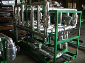
لانس های گاز با تکنولوژی بالا

کاربرد:
برای سیستم های کنار گذر یا زیرگذر در کوره های ریجنراتوری
برای کوره های ریکوپراتوری
بهبود انرژی و شرایط ذوب کاهش دی اکسید کربن و ترکیبات نیتروژن دار کاهش فشار ذوب بر قسمت فوقانی کوره ذوب شیشه بدلیل حجم بالای احتراق و پخش شعله

کاهش طول شعله وشعله ای نرم تر را با استفاده از این مشعل ها به همراه است.

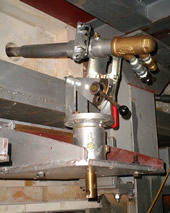
قسمت های مختلف این مشعلها:
- Gas connection
- Scavenging air connection
- Hand wheel adjustment for the nozzle average modification by position change of the gas interior nozzle
- Hand wheel adjustment for regulation of gas quantity separation between the single gas nozzles
- Gas nozzle combination
قسمت های دیگر مشعل جدید گاز سوز:
 |  |
| Burner lance fixation Pos. 1.2 | Burner sealing plate Pos. 1.3 |

.
چارت ابعاد این مشعل های گازی:
The performances listed in the following chart are common upper limits per Regulating Gas Lance and type

| Type | Capacity in KW | Dimensions in mm | in " | in ° | in mm | |||||||
|---|---|---|---|---|---|---|---|---|---|---|---|---|
| (A) | B* | C | D | E | F | G | H | I | (K) | L | ||
| RGB 50 | 500 | 810 | 550 | 40 | 45 | 101 | 35 | 1 | ½ | 15 | 206 | 91 |
| RGB 200 | 1500 | 815 | 550 | 60 | 58 | 101 | 48 | 1½ | ½ | 15 | 206 | 127 |
| RGB 500 | 4000 | 835 | 565 | 70 | 70 | 121 | 60 | 2 | ½ | 15 | 206 | 130 |
| RGB 700 | 6000 | 880 | 580 | 100 | 98 | 141 | 88 | 3 | ½ | 15 | 206 | 140 |
The common gas admission pressures at the burner entry amount between 0,2 and 0,5 bar. But it depends on nozzle arrangement and regulating position of the lances
کوره ذوب با ریکوپراتور سرامیکی
Normally, this glass melting furnace is also equipped with Underport firing.
The details for the above mentioned underport arrangement are valid “regenerative“.
Herewith, the scavenging air is normally out of use, because the burners are non-stop in use.
 Recuperative furnaces with steel recu´s and other glass melting furnaces
The Regulating Gas Lances are installed centrally in the combustion air case.
The air case is designed corresponding to the air temperatures from 20° C to 800° C concerning the customers conditions .
Independently from the use capacities of the gas lances corresponding to the table values, the size of the air case has to be defined, corresponding to the expected air pre-heating. The same is applied to the fixed or variable positioning of the gas lance in the air case.
Standard Types for air cases for 500/800° C air pre-heating:

Dimensions exterior tube
| Type | A | B | C | D | E | F | G | H | J | K | L | M | N | P | S | Weight |
|---|---|---|---|---|---|---|---|---|---|---|---|---|---|---|---|---|
| A | 545 | 465 | 285 | 280 | 250 | 200 | 194 | 14 | 10 | 10 | 100 | 170 | 210 | 4x18 | 40 | ~12 kg |
| B | 545 | 465 | 285 | 280 | 250 | 200 | 224 | 14 | 10 | 10 | 125 | 200 | 240 | 8x18 | 40 | ~13 kg |
| C | 545 | 465 | 285 | 320 | 280 | 220 | 264 | 14 | 10 | 10 | 150 | 225 | 265 | 8x18 | 50 | ~15 kg |
| D | 630 | 550 | 315 | 380 | 340 | 250 | 324 | 18 | 10 | 10 | 200 | 280 | 320 | 8x18 | 50 | ~21 kg |
| E | 630 | 550 | 315 | 430 | 390 | 275 | 374 | 18 | 10 | 10 | 200 | 280 | 320 | 8x18 | 50 | ~24 kg |
| F | 630 | 550 | 250 | 510 | 470 | 315 | 454 | 18 | 10 | 10 | 250 | 335 | 375 | 8x18 | 50 | ~30 kg |
Dimensions interior tube
| Type | Ø R | Weight |
|---|---|---|
| 1 | 125 | ~7,5 kg |
| 2 | 160 | ~9,5 kg |
| 3 | 200 | ~13,0 kg |
| 4 | 230 | ~16,0 kg |
| 5 | 260 | ~21,5 kg |
| 6 | 280 | ~21,0 kg |
Possible combinations
| Capacity in KW | Temperature | Type of exterior tube | Type of interior Tube | Fitting types of lances | ||
|---|---|---|---|---|---|---|
| DLZ / ROB | RGB / GB 50 | RGB / GB 200 | ||||
| 200-300 | 500 °C | A | 1 | |||
| 200-300 | 800 °C | B | 1 | |||
| 280-420 | 500 °C | B | 1 | |||
| 280-420 | 800 °C | C | 2 | |||
| 400-600 | 500 °C | C | 2 | |||
| 400-600 | 800 °C | D | 3 | ( | ||
| 525-800 | 500 °C | D | 3 | ( | ||
| 525-800 | 800 °C | E | 4 | |||
| 750-1100 | 500 °C | E | 4 | |||
| 750-1100 | 800 °C | F | 5 | |||
| 1000-1500 | 500 °C | F | 6 | |||
| 1000-1500 | 800 °C | F | 6 | |||
The HWI-Engineering-Programme
Prior to an offer, it is necessary to clarify the future conditions that could have positive or negative influences.
The more precise the technical details are from the customer, the more optimal is the basis for the later effect.
Therefore, the HWI-questionnaire as well as reliable drawings of the glass melting furnace showing the installation area for the burners, is deemed very necessary.
The HWI-Port-Engineering to the burner port optimisation, assures additional advantages with the economical and ecological operation of your furnace.
You should contact us in the planning phase of a new project or prior to the repair of a furnace in time.
 |  |
Each glass melting furnace has one optimal port-design only.
The following picture shows the serious influences combine or become effective against each other at every firing optimisation.


Benefits:
- Uniform heat radiation over a wide area
- No hot spot in front of the burner outlet
- Robust burner
- Fuel savings with hot air version
Features:
- Sizes from 150kW to 750kW
- Suitable for natural gas, LPG, manufactured gas and light oil
-
Over 10/1 turndown on ratio and 1500% excess air on natural gas
- Ignition by direct spark or premix pilot
- UV flame detection
- Maximum furnace temperature: 1350ºC
- Hot air version available for preheat temperature up to 550ºC
Typical Applications:
- Steel reheating
- Ceramics kilns
- Process heating
- Glass sheet bending

Benefits:
- Rapid and uniform heat distribution
- Robust burner with high turndown and excess air capability
- Controlled firing pattern through choice of outlet
- Fuel savings with hot air version
Features:
- Velocities in excess of 150 m/s
- Sizes from 300 kW to 9000 kW
- Suitable for natural gas, LPG, manufactured gas and light oil
- Dual fuel option available
- Over 10/1 turndown on ratio on natural gas
- High turndown inlet option for up to 5000 % excess air on natural gas
- Choice of outlet: standard refractory quarl or metallic cone: straight, cranked, T-shaped, Y-shaped
- Ignition by direct spark or premix pilot
- UV flame detection
- Maximum furnace temperature: 1600ºC
- Flame detection by single UV cell
- Hot air version available for preheat temperatures up to 600ºC
Typical Applications:
- Heat treatment
- Forging
- Reheating
- Ladle heating
- Tundish heating
- Torpedo heating
- Scrap preheating
- Stress relieving
- Crucibles
- Aluminium melting
- Thermal fluid heaters
- Thermal oxidisers
- Refractory drying units
- Glass tank heating
- Air heating
- Process heating
- Ceramic kilns

Benefits:
-
Outstanding fuel savings of up to 65%
-
Significant reductions in CO2 emission (directly proportional to fuel savings)
-
Reduced levels of NOx
-
Rapid and uniform heat distribution
-
Robust burner with high turndown and excess air capability
-
Improved productivity
-
No need for refractory-lined flues or recuperator due to low exhaust temperatures
-
Reduced exhaust filtering requirements
-
Highly fuel efficient, compact system
-
Better resistance to heat and corrosion than metallic recuperators
-
Attractive payback period
Features:
-
Heat recovery by means of fast cycling compact regenerators working in pairs
-
Typical air preheat: 85% of furnace temperature
-
Staged combustion to reduce NOx levels
-
Velocities in excess of 90 m/s
-
Sizes from 300 kW to 6000 kW
-
Suitable for natural gas, LPG, manufactured gas and light oil
-
Dual fuel option available
-
Over 10/1 turndown on ratio on natural gas
-
Over 1000 % excess air on natural gas
-
Ignition by premix pilot
-
UV flame detection
-
Maximum furnace temperature: 1500ºC
-
Exhausting by means of exhaust fan or eductor
-
Control options: modulating, high/low, on/off or pulse firing
-
Regenerators can be located under or above the burner
Typical Applications:
-
Aluminium melting
-
Heat treatment
-
Forging
-
Steel reheating
-
Strip lines
-
Ladle heating
-
Glass pots
-
High temperature air heating
-
Waste vitrification
-
Ceramic kilns
HOTWORK RECUPERATIVE BURNER (HRB)
In a furnace without heat recovery equipment operating on natural gas at 1200oC with 10% excess air, 63% of the energy input is lost in waste gases and not actually available to the process.
With typical air preheats in excess of 1/3 of the furnace operating temperature, the Hotwork Recuperative Burner has the ability to recover part of this energy by exhausting hot waste gases through its specially designed quarl and over an integral metallic heat exchanger which, in turn, preheats incoming combustion air.
This heat recovery significantly reduces the amount of fuel required for the process and makes the HRB Burner ideal for applications where flue gas temperatures are high and load residence time at high temperature is long, such as forging and heat-treatment furnaces or batch-type furnaces.


Exhausting/Furnace Pressure Control
Since the waste gases exhaust through the burner quarl, there is no need for a conventional flue, which speeds up design and installation of the furnace. The furnace pressure is controlled by an air-driven eductor in the burner flue arrangement.
Accurate pressure control is achieved by varying the volume of air to the eductor which in turn controls the amount of waste gases drawn out of the furnace. No separate fan is required for the air to the eductor as it is supplied by the combustion air fan.
Medium Velocity
The HRB burner has a medium velocity of 70 m/s which, combined with accurate furnace pressure control and careful burner configuration, ensures even temperature uniformity and excellent heat transfer to the load.
Extended Flue Version
In order to increase the residence time of waste gases exhausting through the burner and maximise the exchange of heat between the exhaust gases and the combustion air, the HRB Burners (HRB3.5 to HRB25) can be designed with an extended flue. Please note that these burners require higher combustion air and eductor air pressures. Figures are available from Hotwork Combustion Technology Ltd on request.
Turndown and Excess Air Capability
The turndown of the HRB on natural gas is 10/1 at furnace temperatures below 1200oC. Refer to the Combustion Data Table for turndown at higher temperatures. At maximum air flow and fuel only control, excess air levels better than 500% can be achieved.
Long Flame Design
For applications where extra radiation is required, a long flame design is available.
Fuels
The HRB5 and above are suitable for natural gas, LPG, gas oil (viscosity of 34 sec. Red. 1) or dual fuel arrangement. Smaller sizes are suitable for gas only.
Ignition, Flame Supervision and Automatic Start-up
The HRB Burner is ignited by means of a premix pilot with all fuels. The burner is fitted with a sight glass and a port is provided for a UV scanner to be installed. In order to start the burner automatically and supervise the flame permanently, Hotwork Combustion Technology can also supply flame management equipment if required.
Hotwork Compact Recuperator (HCR)
The heat exchanger inside the HRB Burner is available separately, known as the Hotwork Compact Recuperator, and can be used in conjunction with a hot air burner such as the High Velocity Burner (HV) or the E-Jet Ultra Low NOx Hot Air Burner (EJ_HA). Using the recuperator separately gives the possibility of positioning the burner and the exhaust at different locations, which may be required by certain firing patterns such as around a crucible furnace (burner at the bottom, recuperator at the top). It also enables features of certain burners such as the high velocity of the HV Burner to be used with higher fuel efficiency.

Fuel Savings
The fuel saving from air preheating depends on how much heat is transferred from the exhaust gases to the combustion air (directly related to the exhaust gas temperature). Experience from operating installations indicates that air preheat temperature will be about 35% of the furnace operating temperature.

Thermal ratings and Combustion data |
||||||||
|
Model |
HRB2 |
HRB3.5 |
HRB5 |
HRB10 |
HRB15 |
HRB20 |
HRB25 |
|
|
|
Thermal Rating - Max. (kW) |
57
|
103
|
146
|
293
|
440
|
586
|
733
|
|
|
Air Volume (Stoichiometric) |
57
|
99
|
142
|
283
|
425
|
566
|
708
|
|
|
Air pressure (Stoichiometric) |
37
|
62
|
37
|
70
|
70
|
62
|
62
|
|
|
Eductor Jet Air Volume |
102
|
241
|
241
|
481
|
765
|
991
|
1105
|
|
|
Eductor Jet Air Pressure (mb) |
45
|
70
|
18
|
37
|
43
|
80
|
50
|
|
Natural Gas |
Pressure @ Burner (mb) |
5
|
5
|
5
|
8
|
8
|
14
|
8
|
|
|
Max. Turndown (Stoichiometric) |
10/1
|
10/1
|
10/1
|
10/1
|
10/1
|
10/1
|
10/1
|
|
|
Furnace Temperature 1400oC |
2/1
|
2/1
|
2/1
|
2/1
|
2.5/1
|
3.3/1
|
3/1
|
|
|
Furnace Temperature 1300oC |
4/1
|
4/1
|
4/1
|
4/1
|
6/1
|
8/1
|
5/1
|
|
|
Furnace Temperature 1200oC |
8/1
|
8/1
|
8/1
|
8/1
|
8/1
|
8/1
|
8/1
|
|
|
Furnace Temperature <1200oC |
8/1
|
8/1
|
8/1
|
8/1
|
8/1
|
8/1
|
8/1
|
|
|
Max. Excess Air (%) |
500
|
500
|
500
|
500
|
500
|
500
|
500
|
|
Gas Oil |
Pressure @ burner (bar) |
-
|
-
|
2.2
|
2.4
|
2.4
|
2.2
|
2.2
|
|
|
Max Turndown (Stoichiometric) |
5/1
|
5/1
|
5/1
|
5/1
|
5/1
|
5/1
|
5/1
|
|
|
Max. Excess Air (%) |
500
|
500
|
500
|
500
|
500
|
500
|
500
|
|
|
Atomising Air Pressure (bar) |
2
|
2
|
2
|
2
|
2
|
2
|
2
|
|
|
Atomising Air vol. |
0.187
|
0.187
|
0.187
|
0.187
|
0.187
|
0.187
|
0.187
|
|
|
Max. Flame Length (mm) |
500
|
680
|
1000
|
1120
|
1350
|
1580
|
1650
|
|
|
Long Flame Burner Option (mm) |
800
|
980
|
1300
|
1420
|
1650
|
1880
|
1950
|
|
|
Max. Flame Diameter (mm) |
150
|
170
|
170
|
220
|
250
|
280
|
300
|
The data provided is for guidance only and could vary slightly due to manufacturing tolerances
* Required oil supply pressure: normally 5.5 to 6.8 bar
The data provided on this page is for information only and does not form part of any contract. Due to our continued commitment to research and development, we reserve the right to modify specifications or dimensions without notice. The improper use of combustion equipment can result in a condition hazardous to people and property. Users are urged to comply with national and local standards.
Ratio Matic : Winnox : Therm Air / Ratio Air : Vortometric : Air Heat : Linnox : AH-MA : Flue Fire.
Furnace Burners From Therm Jet high-velocity burners to Therm Thief radiant tube burners, Eclipse furnace type burners improve continuous or batch operation productivity while reducing energy costs and controlling emissions.
- Furnace Burners (Direct Fired)
Therm Jet : TJSR (Therm Jet Self - Recuperative : Furnnox : Extensojet : Therm Thief : Bayonet Recuperators : Bayonet - Ultra Recuperators : SER (Auto Recpa)
Oxygen - Fuel Burner Eclipse offers a full line of industry proven oxygen - fuel burners to the glass and other high temerature process markets.
Primefire100 : Primefire 300 : Primefire 400 : Primefire Forehearth :
Air Oil Burners fEclipse affers air-oil burners suitable for both underport and througport firing.
Series O3FA : Series GTCPA : Series WTPF.
Air - Gas Burners fEclipse air -gas burners can be used for side - of - port, underport and throughport firing.
Brightfire : 04V : WRASP : GTNG : WGD.
Immersio Burner fImmersion burners are used to hea a variety of liquids, from water to cleaning solutions to cooking oils. Since each liquid has a different heat transfer capability, it's important to apply the correct immersion eating burner technology to optimize the combustion system.: Immerso Jet : Immerso Pak : SMJ Centrifugal Blowers : Hermetic Gas Boosters.
FFlame Monitoring fEclipse offers a full line of single and multiple burner sequence controllers and relays. In addition, several flame rods, scanners and remote displays are available for use with these devices.
Shut - Off Valve fEclipse manual and automatic reset shut - off valves are designed to shut off the gas supply to a combustion system in the event of an electrical power failure or the opeing of an interlocking switch in the combustion system. All valves are UL listed, FM approved, and CSA certified.
 |
 |
 |
 |
 |
 |
 |
 |
 |
 |
 |
 |
 |
 |
|
 |
 |
|
 |
 |
 |
 |
 |
 |
 |
 |
|
 |
|
|
|
|
Immerso Pak V2.00 Replacements/Spare Parts for Configured Products.
IP 004 : 10002242-1 Flame Rod :10007506 Actuator Siemens : 10009974 Actuator Siemens : 10912 Motor Actuator : 11080 Regulator Ratio : 11132 Filter Media : 14191-1 Orifice Plate : 14191-16 Orifice Plate : 14191-19 Orifice Plate : 14191-31 Orifice Plate : 14191-5 Orifice Plate : 14191-5 Orifice Plate : 14887-13 Combustor Alloy Tube : 15273-4 Actuator : 17054 Gasket Body : 20440 Switch Air Pressure : 20475 Switch Air Pressure : 20475 Switch Differential : 20518 Motor : 20554 Motor : 20900 Zero Governor : 21057 Motor : 21472 Motor : 21495 Motor : 21631 Motor : 21727 Motor : 22735 Actuator : 22755 Actuator : 23045 : Plug Spark : 7033-2 Nozzle Machined : ACT004A1B1A1A Actuator Rotary : ACT004A2B1A1A : Actuator Rotary ACT004A3B1A1A : ACT004A4B1A1A : Actuator Rotary :
IP 005 : 10002322 Spark Plug : 10007506 Actuator Siemens : 10009974 Actuator Siemens : 10912 Motor 11132 Filter Media : 11579 : Motor : 12109 Motor : 12570 Motor : 13312-10 Flemrd : 14934-10 Orifice Plate : 14934-13 Orifice Plate : 14934-15 Orifice Plate : 14934-17 Orifice Plate : 14934-18 Orifice Plate : 14934-2 Orifice :15273-4 Actuator : 15939 Ratio Regulator : 20362-7 Orifice Plate : 204007 Combustor Alloy Tube : 20422 Mounting Gasket : 20440 Switch Air Pressure : 20475 Switch Differential : 20520 Motor : 20527 Motor : 20556 Motor : 21059 Motor : 22735 Actuator ; 22755 : Actuator : 7133-1 Nozzle Thermjet TJ050 : ACT004A1B1A1A Actuator Rotary : ACT004A2B1A1A Actuator Rotary : ATC004A3B1A1A Atctuator : ACT004A4B1A1A Actuator :
IP 006 :10002322 Spark Plug : 10007506 Actuator Siemens : 10009974 : Actuator Siemens : 10912 Motor Actuator :11080 Regulator Ratio :11132 Filter Media : 12033 Motor : 13101 Motor : 13312-9 Flmrd : 14188-26 Orifice Plate : 14188-27 Orifice Plate : 14188-27 Orifice Plate : 14188-8 Plate Orifice : 14802-11 Orifice Plate : 14188-8 Plate Orifice : 14802-11 Orifice Plate : 14932 Gasket Mounting : 15273-4 Actuator : 15939 Ratio Regulator : 19999 Ratio Regulator : 20440 Switch Air Pressure : 20475 Switch Differential : 20520 Motor : : 20528 Motor : 20556 Motor : 20859 Tube Combustor : 21059 Motor : 21473 Motor : 22735 Actuator : 22755 Actuator : 3997-1 Nozzle Machined Thermjet Size 4 Burner : ACT004A1B1A1A Actuator Rotary : ACT004A2B1A1A Actuator Rotary :
IP 008 : 10007506 Actuator Siemens : 10009974 Actuator Siemens : 10027 Gasket Mounting : 10039-5 Orifice Plate : 10912 Motor : 11128 Filter Media : 14188-19 Orifice Plate : 14188-20 Plate Orifice : 14188-23 Plate Orifice : 15273-4 Actuator : 20311 Ratio Regulator : 20312 Ratio Regulator : 20440 Switch Air Pressure : 20475 Switch Air Pressure : 22735 Actuator : 22755 Actuator : 23045 Plug Spark : 7038-1 Nozzle Thermjet TJ300 : ACT004A1B1A1A Actuator Rotary : ACT004A2B1A1A Actuator Rotary :
IP 010 : 10007506 Actuator Siemens: 10009974 Actuator Siemens : 10027 Gasket Mounting : 10039-1 Orifice Plate : 101279-1 Tube Combustion : 10315 Ratio Regulator : 10912 Motor : 11128 Filter Media : 14188-19 Orifice Plate : 14188-20 : Plate Orifice : 15273-4 Actuator : 16770 Motor : 19990 Ratio Regulator : 20360 Motor : 20440 Switch Differential : 21478 Motor : 22735 Actuator : 22755 Actuator : 23045 Plug Spark : 7038-1 Nozzle Thermjet TJ300 : ACT004A1B1A1A Actuator Rotary : ACT004A2B1A1A Actuator :
IP 012 : 10001732-1 Cone Diffuser Size 5 : 10007506 Actuator Siemens : 10009974 Actuator Siemens : 10027 Gasket Mounting : 101279-1 Tube Combustion : 10315 Ratio Regulator : 10912 Motor Actuator : 11128 Filte Media : 14188-1 Orifice Plate : 14188-4 Orifice Plate : 14188-6 Plate Orifice : 15273-4 Actuator : 16770 Motor : 19990 Ratio Regulator : 20360 Motor : 20440 Switch Air Pressure : 20475 Switch Differential : 21478 Motor : 22735 Actuator : 22755 Actuator : 22755 Actuator : 23045 Plug Spark : 7038-1 Nozzle Thermjet TJ300 : ACT004A1B1A1A Actuator Rotary : ACT004A2B1A1A Actuator Rotary :
Solenoid Valve for Air, Natural Gas, Propane & Butane110/120 V.
General Purpose Gas Shut - off Valve. L8040H7 : L8040H8 : L8040G21 : L8040G21 : L8040G22 L8214G20 L8040G23 JB821435 JB821450 JB821460 JB21470 JB821480:JB821490 : JB821440 Part No. 20167 20168 20169 20170 20171 20172 20173 20174 20175 20176 20177 20178 20179
220/240V General Purpose Gas Shut off Valves L8040H7 20167-1 : L8040H8 20168-1; L8040G21 20169-1 ; L8040G22 20170-1 ; L8214G20 20171-1 ; L8040G23 20172-1
220/240V. General Purpose Gas Shut off Valve -Continued JB821435 20173-1 ; JB821450 20174-1; JB82146020175-1 ; JB821470 20176-1 ; JB821480 20177-1 ; JB821490 20178-1 ; JB821440 20179-1
110/120V. General Purpose Gas Shut off Valve - with Visual Position Indication JB821435VI 20448 ; JB821450VI 20451 : JB82146oVI 20453 : JB821470VI 20455 : JB821480VI 20457: JB821490VI 20459 : JB821440VI 20461
110/120V. General Purpose Gas Shut off Valve - with Visual Position Indicaton and Proof of Closure Switch JB821435C 20449 ; JB821450C 20452 ; JB821460C 20454 : JB821470C 20456 : JB821480C 20458 : JB821490C 20460
220/240V. General Purpose Gas Shut off Valves - with Visual Position Indication and Proof of Closure Swith : JB821435C 20449-1 : JB821450C 20452-1 : JB821460C 20454-1 : JB821470C 20456-1: JB821480C 20458-1: JB821490C 20460-1 : JB821440C 20462-1 :
110/120 Vent Valve L8214G33 20161 : JB821453 20162 : JB821463 20163 : JB821473 20164 : JB821483 20165 : JB821493 20166
220/240 Vent Valves L8214G33 20161-1 ; JB821453 20162-1 : JB821463 20163-1 ; JB821473 20164-1 JB821483 20165-1: JB821493 20166-1
Replacement Coils 120V. 20412 20413 20414 20416 20417
Replacement Coils 240V. 20412-1 ; 20413-1; 20414-1 ; 20416-1 ; 20417-1
Ratio RegulatorsNPT : ES365 19997 ; ES366 15939 ; ES363 20312 ; ES368 10315 : ES369 10316
Ratio Regulators Rp (Metric) : ES365M 19998 ; ES366M 19999 ; ES363M 20311 : ES368M 19990 ; ES369M 19989
Ratio Regulators NPT R400Z 15685 : R500Z11080 :
Ratio Regulators Rp (Metric) R400ZM 21313 ; R500ZM 20900
Gas Pressure Regulators Model 043-B : Regulator 043B-182, 3/8 in. NPT, Cast Lron Body , 125 psi, IrV, Spring : 6- Part No. 16150-B4 : Regulator , 043B-182, 1/2 in NPT, Cast Iron Body, 125 psi, IrV, Spring : 6- Part No. 16150-B5 : Regulator , 043B-182, 3/4 in. NPT Cast Iron Body, 125 psi, IrV, Spring : 6-14 Part No. 16150-B1 : Regulator, 043B-182, 1 in. NPT, Cast Iron Body, 125 psi, rV, Spring 6-14 Part No. 16150-B3
Gas Pressure Regulator Model 143-80-2 :143-80-2, 3/4 in NPT, IrV 6-14 in. wc Spring, 3/8 in. orifice Part No. 16151-1 : 143-80-2, 1 in. NPT, IrV 6-14 in.wc Spring 3/8 in. orifice Part No. 16151-2 : 143-80-2 1.1/4 in NPT, Irv 6-14 in. wc Spring, 3/8 in. Orifice 16151-3
Gas Pressure Regulator Model 243-RPC-B : 243-Rpc-B 2 in. NPT, 1-5 psi Spring, 1.1/4 in. orifice Part No. 16152-13 : 243-Rpc-B, 2 in. Flg Spring : 1.0-5.0 psi (white) orifice : 1.1/4" Prat No. 16152-14
Gas PressureRegulator Model 243-8-1 : 243-8-1, 1.1/4 in NPT Spring : 6-14 in. wc Part No. 16152-5 : 243-8-1, 1.1/2 in. NPT spring : 6-14 in. wc (Green - Black) 16152-6: 243-8-1, 2 in NPT Spring : 6-14 in wc (Green/Black) orifice 16152-7 :
Gas Pressure Regulator Model 243-8-2 : 243-8-2, 1.1/4" in NPT, IrV Spring : 6-14 in.wc (Green-Black) Part No. 16152-8 ; 243-8-2, 1.1/2 in. NPT, IrV spring : 6-14 in.wc (Green Black) : 243-8-2 ;2 in NPT, IrV Spring : 6-14 in. wc orifice : 1/2 in Part No. 16152-10
Gas Pressure Regulators : RV12LT 17127-1 : RV20VL 15027 : RV20VL 17127-6 : R400S 17127-8 : R500S 17127-9 ; RV48L 12271 ; RV52 12274 ; RV52 12276 : RV53 12277 : RV53 12278 : RV61 12279 : RV61 12280 : RV81 12282 : RV81 12284 : RV91 12285 : RV91 12286 : RV111 12288 : RV111 12290; 325-5A 10866 ; 325-5A 10888 ; 325-5A 10897
Zero Governors : R600Z Zero Governor, 1 in. NPT, R600Z Part No. 21691 : Zero Governor , 1.1/2 in NPT. 21Odz Part No. 21692 : Zero Governor, 2 in NPT, 210ez 21693 : Zero Governor, 3 in, NPT, 210gz Part No. 21694 :
Stock Ratio Regulatior size 2" ES368M Eclipse: Ratio Regulator 1" 1PSI ES366 Eclipse; Series Locktite Shut off valve 220 V LT-IS-4 : Auti Matic
http://combustion.in.th/product%20CBT.htmlA review of Supplemental Oxygen Methods for Glass Melting
Increasing the amount of Oxygen in air from its initial 21% significantly
increases the flame temperature achieved with any fuel. For example, natural gas
burned in air has a flame temperature of 3520 F while the flame temperature of
natural gas burned in 23% O2 is 3640 F.
This effect is shown in figure
below

Higher flame temperatures in the glass furnace improve the heat transfer to the batch and glass. This is due to the fact that all three heat transfer mechanisms, conduction, convection, and radiation, are flame temperature dependent:
Conduction: Q (Tf – Tp)
Convection Q (Tf – Tp)
Radiation Q (Tf –
Tp)
where: Tf = Flame Temperature
Tp = Product (Lime) Temperature
At glass melting temperatures radiation is the dominant mode of heat transfer. The heat transfer rates for conduction and convection are linear with the difference between the glass and the flame temperature. The heat transfer rate due to radiation is proportional to the difference between glass and flame temperature, each raised to the fourth power. Oxygen increases the flame temperature, which greatly increases radiation, the already dominant mode of heat transfer. Thus with oxygen enrichment, more heat is absorbed by the product, less heat is lost in the exiting combustion gas, and the combustion process becomes more efficient
 Oxygen Enrichment:
With this technique, oxygen is injected into the main combustion air header well ahead of the delivery point to the furnace. This pre-mix of oxygen is most common on recuperative furnaces or unit melters that have many such delivery points (hot or cold air burners) or on regenerative melters where it is desirable to use the oxygen to enhance the entire combustion process in a consistent manner. Experience is needed to deliver the right amount of heat to the right zones and to ensure safe application of the Oxygen
 Oxygen Lancing:
This method has historically been the most cost-effective way to use oxygen to supplement air-fuel combustion. The strategic injection of oxygen beside, beneath or through air-fuel flames has allowed glass melters to reach campaign objectives in terms of pull rate, fuel efficiency and glass quality. The benefits of oxygen lancing accrue from having the oxygen mix with fuel where it is most needed; namely in oxygen-starved areas of the combustion space or in the under-side (glass surface side) of the air-fuel flames where flame temperature has the greatest impact on heat transfer to the melt. Knowing how many lances, where to place them and flow rates to use, allow us to deliver the most cost effective solution
 Oxygen Boosting:
This method of using supplemental oxygen is relatively new to glass manufacturers and has been enabled by the emergence of superior oxy-fuel burner offerings developed for the 100% oxy-fuel conversion of melters. The boosting concept uses oxy-fuel burners positioned within the air-fuel melter to increase production, quality, efficiency and furnace stability. Depending on the needs of our customers we can tailor the operation to deliver the benefit(s) desired. Oxy-fuel boosting is typically used to increase pull rate on a furnace that is at capacity or that has been crippled due to a failure or loss of effectiveness of the air-fuel combustion system. Payback for the technology is often less than three months. The advantages of our boost technology are so significant that many furnaces, which used Air Products’ boost at the end of the previous campaign to address furnace limitations, are rebuilt and come on-stream using boost
Here, the high temperature flames of oxy-fuel combustion are placed over the cold batch to create a tremendous amount of heat transfer. The result is early batch glazing and significantly enhanced melt run-off; this superior melt rate then allows for an increase in production or a reduction in over all fuel.Talk to us to find out which of these, or other, techniques is right for you. We continue to develop new technologies to improve glassmaking
http://www.airproductsafrica.co.za/wp-content/uploads/2008/07/oxytech01.gif مشعل اکسیژن سوز
 مشعل تشعشعی
http://www.directindustry.com/prod/eclipse/oxy-fuel-natural-gas-burners-21978-453057.html

High-Performance, Energy-Efficient Burner System Developed
An outstanding example is the “Regenerative Burner System” we have developed and sold that can efficiently recover waste heat in industrial furnaces. In the “Regenerative Burner System,” two burners, each containing a heat storage vessel, alternate in combustion in intervals of less than a minute. When one burner is combusting, its exhaust goes out through the other burner's heat storage vessel. When the other burner combusts, for combustion air it uses the waste heat warmed up in the heat storage vessel. This allows it to obtain air heated to at least 1,000 degrees Celsius from 1,200 degrees Celsius exhaust and thus save approximately 50% in energy.
We are also developing natural gas burners for glass melting furnaces for manufacturing glass for bottles, automobiles, and construction materials, and more and more customers are adopting these burners as a way to dramatically reduce CO2 emissions.

Combustion Tec Burners
A Low NOx Adjustable Air-Gas Burner for Glass Furnaces
BrightfireTM Burner


Primefire® Series Oxy-Fuel Burners
Primefire® 100 Series Oxygen-Gas Burner


Primefire® 100 Series Burner Combustion Tec Lab Firin
Primefire® 100 Oxy-Gas Burners


Primefire® 100 Series Oxygen-Oil Burners


Primefire® 300 Series Burners

Primefire® Series Oxygen-Fuel Furnaces

Primefire 400 High Efficiency Low Nox Oxygen-fuel Burner

Fuel Preheating Zone
Flame Zone
Metering and Flow Controls
Gas and Oxygen Metering and Flow Control Train

Main Gas Train

Individual Flame Development

Oxygen Enriched Air Staging Technology to Reduce NOx Emissions
OEAS Process for Endport Regenerative Furnaces

OEAS Process for Sideport Regenerative Furnaces

Oxygen-Gas Boosting
Oxy Boosting/Side Fired Regenerative


Oxy-Gas Boosting Metering Panel


The purpose of Eclipse is to pioneer the development and implementation of innovative technologies to provide industry worldwide with the cleanest heat possible.
Combustion Systems and Components
Combustion Specialists for the Glass and Ceramics Industry
CCTV System

CCTV Software Applications Digital Recording

CCTV Software Applications-cont’d Thermal Imaging

Oxygen – Gas Forehearth Combustion Systems

- Gas Flow Rates


The Eclipse Inc. Series 0400 hot air nozzle-mixing burners are suitable for many applications ranging from small glass day tanks, float glass furnace working ends, refiners and distributors, to large multi-burner recuperative furnaces.
A recuperator or other means provides preheated combustion air to the burner. Using combustion air preheating will lead to increased fuel savings. The Series 0400 burners can be either side or end fired on several types of continuous furnaces. Any clean industrial gas and/or grade of fuel oil of suitable viscosity may be burned.
Features: Hot/Cold Air - Combination Fuel Oil & Gas
o Recuperative Furnace Operation
o Long life stainless steel construction
o Standard models to 1200 Degrees F (649 Deg. C), special models to 1400 Degrees F (760 Deg. C)
o Improved adjustable gas orifice for better flame shape control
o Oil uses atomizing air or steam to 40 psig (2.76 bars)
o Variable oil flame shaping capability
o Pre-heated combustion air provides fuel savings up to 45%
o Adjustable air for additional flame shape control or capacity requirements.
http://www.directindustry.com/prod/eclipse/nozzle-mix-dual-fuel-burner-21978-452911.html
Combustion System
We design and supply combustion systems used in various industrial furnaces.
Under port burner
Piping unit
We supply combustion systems for various furnace types whose combustion capabilities differ in accordance with their capabilities.
We have a track record for using a variety of fuels, regardless of gas or liquid, and can deal with fuel conversion away from the current fuel.
http://www.ihara-furnace.co.jp/english/en_product/pro-02_01-c.html
ذوب در کوره های شیشه با مشعل های جدید
http://www.4shared.com/document/Ra7xZVT2/___.html
برای دانلود مقاله بالا بر روی ادرس فوق کلیک فرمایید
علیرضا حسینی-فرایند ذوب شیشه
.: Weblog Themes By Pichak :.

