ادامه مطلب
پنجرههای هوشمند امروزی چندان مقرونبهصرفه نیستند. شرکت سولادیم موفقشده با استفاده از ترکیبات تازه و جدیدترین تکنیکها شیشههای هوشمند ارزان و با قابلیتهایی منحصربهفرد ایجاد کند.

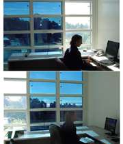
استفاده از پنجرههایی که میتوانند با کاهش یا افزایش جذب نور روشنایی و دمای خانهها را تنظیم کنند میتواند تأثیر بهسزایی در کاهش مصرف انرژی و هزینههای خانوار داشته باشد. با این حال به کارگیری این پنجرهها با هزینه تولید بالای 10دلار برای هر مترمربع در منازل و دفترهای کار چندان مقرونبهصرفه به نظر نمیرسد.
به گزارش تکنولوژی ریویو، شرکت Soladigm موفق شده است با به کارگیری تکنیک تازهای ساخت شیشههای هوشمند حساس به تغییرات جریان الکتریکی -الکتروکرومیک- را بسیار مقرونبهصرفهتر از قبل کند. این شرکت رقم دقیقی را عنوان نکرده اما به نظر میرسد هزینهها حداقل 80درصد کاهش داشته باشند.
پنجرههای هوشمند امروزی چندان مقرونبهصرفه نیستند. شرکت سولادیم موفقشده با استفاده از ترکیبات تازه و جدیدترین تکنیکها شیشههای هوشمند ارزان و با قابلیتهایی منحصربهفرد ایجاد کند.
استفاده از پنجرههایی که میتوانند با کاهش یا افزایش جذب نور روشنایی و دمای خانهها را تنظیم کنند میتواند تأثیر بهسزایی در کاهش مصرف انرژی و هزینههای خانوار داشته باشد. با این حال به کارگیری این پنجرهها با هزینه تولید بالای 10دلار برای هر مترمربع در منازل و دفترهای کار چندان مقرونبهصرفه به نظر نمیرسد.
به گزارش تکنولوژی ریویو، شرکت Soladigm موفق شده است با به کارگیری تکنیک تازهای ساخت شیشههای هوشمند حساس به تغییرات جریان الکتریکی -الکتروکرومیک- را بسیار مقرونبهصرفهتر از قبل کند. این شرکت رقم دقیقی را عنوان نکرده اما به نظر میرسد هزینهها حداقل 80درصد کاهش داشته باشند.
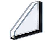
در این روش لایهای رسوبی متشکل از دو فیلم شفاف اکسیده با قابلیت رسانایی بالا که یک لایه یونی، یک الکترولیت و یک لایه الکتروکرومیک را در برگرفتهاند، میان دو صفحه شیشهای تعبیهشده است. با به کارگیری یک جریان الکتریکی با ولتاژ پایین یونها از محفظه نگهداری خارج خواهند شد و با گذر از الکترولیت به لایه الکترومیک خواهند رسید. برخورد یونها با این لایه الکتروکرومیک جذب یا بازتاب نور را باعث خواهد شد و میتواند به پنجره ظاهری تیره بدهد. با تغییر جهت جریان الکتریکی میتوان یونها را به فضا اولیه برگرداند و ظاهری روشنتر همراه با ورود نور بیشتر را به پنجره داد.
مطالعه روی تعدادی از ساختمانهای تجاری در 5 شهر مختلف نشان میدهد استفاده از این پنجرهها میتواند هزینههای گرمایش، تهویه هوا و تهویه مطبوع را سالانه تا 25درصد کاهش دهد.
رائو مالپوری مدیر عامل شرکت سولادیم میگوید: «راز کاهش هزینهها و بهبود کیفیت در استفاده از مواد صحیح و بهرهگیری از تازهترین تکنیکها نهفته است». این شرکت ساخت پنجرههای هوشمند را با استفاده از اکسیدتنگستن آغاز کرد اما داغ شدن شیشهها به دلیل فعل و انفعالات شیمیایی و جذب پایین پرتوهای زیرقرمز توسط این پنجره باعث شدند استفاده از مواد جدید مورد توجه قرار بگیرد.
در مراحل بعدی استفاده از لایه الکتروکرومیک بر پایه واکنش متقابل میان منیزیوم و یونهاى هیدروژن جایگزین اکسیدتنگستن شد و علاوه بر این آلیاژ آنتیموان با عناصری مانند مس یا نقره در مقابل یونهای لیتیوم به کار گرفته شد. این واکنشها نهتنها حرارتی تولید نمیکنند بلکه میتوانند با دقت بالایی جلوی ورود پرتوهای نور مرئی و زیرقرمز را به محیط بگیرند.
علاوه بر این روشی پیشبینی شده که میتواند با استفاده از پنجرههای هوشمند میزان ورود نور مرئی و زیرقرمز نزدیک را کنترل کرد و از تابش خورشید در روزهای سرد زمستان حداکثر استفاده را برد.
منبع:technologyreview
· كاربرد پنجره در صنايع ساختماني
· رابطه پنجره و مصرف انرژي
· رويكردهاي قديم و جديد
· پنجره هاي هوشمند :
- انواع مختلف
- مقايسه
- تكنولوژي انتخابي
تقسيم بندي شيشه هاي مصرفي در ساختمان :
شيشه پنجره – دزدگير سقف – شيشه هاي پاسيو
چرا از پنجره و شيشه در ساختمان ها استفاده مي كنيم ؟
- برقراري ارتباط مفيد بين داخل و خارج ساختمان ( از لحاظ ديده شدن يا نشدن )
- آسايش بهتر با ايجاد امنيت و ايمني
- مانعي در برابر گرد و غبار , باران , سرما و آلودگي هاي صوتي
- منبع بسيار خوبي است جهت استفاده بهينه از نور خورشيد . بطوريكه : شدت نور حاصله توسط لامپ هاي الكتريكـي در حـدود 200-1000 LUX و براي منبع خورشيـد 10.000-100.000 LUX مي باشد , در نتيجه تعدد و استفاده از انواع مختلف پنجره مي تواند علاوه بر زيبايي , مصرف بهينه انرژي را همراه داشته باشد .
ا ين مبحث جزء مباحث جديدي مي باشد كه حتي بعنوان ابزارهاي نوين در مهندسي فروش استفاده مي گردد .
پس با انتقال نور بيشتر به داخل , با افزايش حرارت ساختمان مواجه خواهيم بود .
بطور كلي مكانيزم هاي تبادل حرارتي انرژي عبارتند از :
هدايت
همرفت
تشعشع
كه البته اين مسأله براي ما مطلوب نمي باشد . زيرا ما به حرارت پائين نياز داريم و حرارت بالا در داخل ساختمان مشكل ساز مي باشد . به عبارت ديگر هدايت حرارتي شيشه در كل مشكل ساز مي باشد , چه از بيرون گرما به داخل وارد شود و چه در فصل سرما گرماي داخل به بيرون منتقل شود . از ميان اين عوامل , مورد تشعشع درخصوص پنجره ها بيشتر مطرح مي باشد . ما بايد از امواج نوراني خورشيد به نحوي استفاده كنيم كه مفيد باشند .
به علت مشكل بودن كنترل انتقال مي بايست با روشهاي مختلف تنها 3/1 اتلاف انرژي را كه CONVECTION و CONDUCTION مي باشد را متوقف سازيم و نمي توان جلوي 3/2 RADIATION را گرفت .
تمامي مباحث از اين قبيل به نوعي به نور خورشيد مربوط مي گردند . بطوريكه گسترده وسيعي از تشعشعات را شامل مي شود .
چشم ما فقط نور مرئي را تشخيص مي دهد : 400 nm - 700 nm
در واقع چون 51 % قسمت انرژي خورشيدي در منطقه مادون قرمز قرار دارد , لذا تكنولوژي جديد بر روي كنترل اين قسمت استقرار مي باشد .
پس مي بايست منحني طيفي شيشه را تغيير دهيم كه در نتيجه :
1- آسايش بيشتر فراهم مي گردد . بطوريكه اگر نور زياد باشد , نمي توان از صفحه مانيتور كامپيوتر يا تلويزيون به علت خيره كنندگي نور بازتابش شده استفاده بهينه نمود .
2- كمك به طراحان و معماران ساختمان را همراه دارد در جهت زيبايي و مصرف بهينه انرژي
3- كمك به پاكيزگي طبيعت , اتلاف انرژي كمتر و آلودگي كمتر
LOW-E GLASS :
سيستم هاي ديناميكي جلوگيري از ورود گرما به داخل ساختمان عبارتند از :
1- قرار دادن پرده در جلوي پنجره
2- استفاده از سايه بان
3- استفاده از شيشه هاي رنگي يا كدر
شيشه هاي LOWE در ناحيه هاي مرئي كاملاً شفاف هستند , ولي در ناحيه هاي غير مرئي ( مادون قرمز ) عبور نور جزئي از خود نشان نمي دهند .
تعريف SUPERWINDOW :
GLAZING FOR U-FACTOR < 0.15
پنجره هايي كه از 2 , 3 و يا چند جداره تشكيل شده اند و گاهاً بين آنها خلا مي باشد .
روند پيشرفت اين تكنولوژي :
1973 TYPICAL WINDOWS U=0.85
2002 TYPICAL WINDOWS U=0.45
2020 IEB WINDOWS U=0.1
فقط حدود 5 تا 10 % كل ساختمان از شيشه تشكيل مي شود , ولي حدود 50 – 60 % اتلاف انرژي از همين حجم كم صورت مي پذيرد , همواره بشر به سمت راحتي و آسايش پيش مي رود . لذا دنبال نوعي شيشه مي باشد كه خود بصورت هوشمند قابليت گذر , عبور و .... را تنظيم نمايد .
انواع تكنولوژي شيشه هاي هوشمند :
1- شيشه هاي فتوكروميك : با برخورد نور UV تيره شده , هوشمند محسوب نمي شوند و كنترل آن در دست ما نمي باشد .
2- شيشه هاي ترموكروميك : شيشه هائي كه رنگشان با گرما تغيير مي كند و براي محدوده دمائي خاص تنظيم مي گردد .
3- شيشه هاي گس كروميك : شيشه هاي چند جداره ( حداقل دو جداره ) كه پوششهاي معيني بر روي آنها اندوده شده و بين لايه ها از گازهاي مختلف استفاده شده است .
4- شيشه هاي ترموكروميك : بدون جريان الكتريكي و بدون فرمان USER استفاده مي شوند و حاوي مواد پليمري خاص مي باشد كه در دماي پائين به هم ادغام شده و در دماي بالا منبسط و پراكنده مي شوند كه اين خود باعث پراكندگي بيشتر نور مي گردد .
5- شيشه هاي ليكوئيدي : با عبور نور از ميان لايه هاي مختلف آن وضعيت هاي زير برقرار مي باشد :
6- شيشه هاي SPD : مكانيزم عملكرد آن بدين صورت مي باشد .
که تست ولتاژ حدود V 100 كار مي كنند و در سقف اتومبيل استفاده مي شوند . نمونه آن در شركتهاي كره اي مورد استفاده قرار گرفته است .
7- شيشه هاي الكتروكروميك : شيشه هايي كه با جريان الكتريكي رنگشان تغيير مي نمايد . فقط وضعيت ON يا OFF دارند و حالت وسطي براي آنها باقي نمي ماند . اما در مورد اين شيشه ها حالت دلخواه مياني وجود دارد كه از مزاياي آن مي توان به :
1 – حافظه دار بودن آنها, مثلاً وقتي شيشه را به رنگ آبي در آوريم و ناگهان برق قطع شود, حدود 2 روز طول مي كشد تا رنگ آن تغيير كند .
2 – ولتاژهاي مصرفي مورد نياز آن پايين مي باشد . اينها شيشه هاي چند لايه اي هستند كه هر لايه نقش ويژه اي ايفا مي كنند .
الكترودها
الكتروليت
تثبت كننده يونها
الكترودها
در اينجا 2 مشكل عمده در تجاري شدن اين نوع شيشه ها وجود دارد :
1– هزينه مالي: چون داراي قيمت توليدو آزمايشات بسيار بالايي مي باشد . ( هر مترمربع 1000 دلار )
2 – بحث تكنولوژي : به علت دارا بودن فن آوري بسيار پيشرفته و پيچيده (HIGHT TECH ) در اختيار قرار گرفتن آن بسيار دشوار مي نمايد .
در پايان ذكر اين نكته ضروري مي باشد كه تا كنون از اين نوع شيشه ( نوع آخر ) تنها در مقياس كوچك آزمايشگاهي توليد گرديده است و تحقيقات جهت ادامه روند توسعه آن همچنان ادامه دارد .
|
||||||
| Description | ||||||
| The completed tin bath roof is assembled by bridge tile, support tile and plug tile combining four side supporting structure, which increases the stability of the whole structure. Working face adopts sintered sillimanite and non-working face lightweight insulating brick, hangers are heat-resistant alloy, and sidewall is lightweight insulating brick. The advantage of this structure is that there are no vertical joints which can avoid spot defect on glass effectively. This kind of roof system is used in float tin bath and other kind of kiln roof where working temperature is lower than 1300℃. |


ادامه مطلب


AGC's alkali glass manufacturing method lets glass float over molten metal to produce highly uniform glass
The company has a 20-year history producing thin sheets of glass. Only in April, the company announced glass sheets of 0.28 mm thick soda-lime glass substrate for touchscreens. Soda-lime glass is composed mainly of silicon dioxide, sodium oxide, and calcium oxide, and is used widely in construction, automotives, and many types of electronic devices
The 0.1 mm sheets are alkali-free glass, composed mainly of silicon dioxide, boron oxide, and aluminum oxide, is free of alkaline elements such as sodium and potassium, and is used widely as substrates for TFT-LCD and OLED
Toshiro Ueda, general manager of corporate communications and investor relations, said the glass is being investigated by car manufacturers for use in dashboards but declined to name those interested
Ueda claims that, "Our achievements in thin durable glass has attracted many other application areas, especially for increasingly thin and energy saving displays and OLED lighting"
Thin sheet glass is expected to be used in such products due to its flexible shaping and light weight, as well as basic characteristics of glass such as transparency, electrical insulation and resistance to heat, chemicals and gases
ادامه مطلب


Services of the German Floatglass Technology network
Thanks to the team of experts within the network and the engineering
know-how provided by it, GFT is able to plan and design
- melting furnaces,
- float baths,
- cooling channels,
- cutting lines and
- glass storages,
according to your wishes.
The GFT group has specialized in realizing turnkey float baths - ranging from the very first idea, over delivery, installation and commissioning as well as training of staff (for the first glass and production), up to continuous optimization of your overall plant. All machines for your float bath required to produce float glass, such as
- Control system of front and back Tweel
- Dross Box
- Toproller (suspended / standing)
- Video equipment; Dolly (supended / standing)
- Pushers / Fences / Flags
- Venting for special-purpose glass
are manufactured by GFM
GmbH (subsidiary company) in Southern Germany.
In addition to that, in co-operation with GFP GmbH, we provide the entire project management for new constructions of melting furnaces as well as cold repairs for the hot end area.
All steel elements and steel constructions like:
- Support Steel Structure with transformer platform
- Tin bath casing
- Tin bath roof casing
- Side sealing boxes
- Coolers,
- Tin coolers,
- Spout(-casing),
- Cooler lances
are manufactured by our co-operation partner Forster Stahl- und Anlagenbau
GmbH in Mantel, Southern Germany. The Forster
Stahl- und Anlagenbau GmbH is fellow partner of the neighbouring company
GFM GmbH (one conjoint
production facility) and our exclusive supplier.

ادامه مطلب
ECONOMICAL OPERATION OF UNDUSTRIAL GAS APPLIANCE
In industrial gas appliance there are heat-treated products from the metallurgy and mechanical engineering field moreover from glass and ceramic field and many others:
- steel products, cast stocks, engineering steel, metal sheets, wires
- products of non ferrous metals (aluminium, copper, brass)
- utilitarian and packaging glass, laboratory and flat glass…
- products for building industries (lime, cement, bricks, roofing, etc.)
- utilitarian and sanitary ceramics, artistic ceramics, tiles, fireproof materials
- oil industry products, commodities for colour production
Industrial appliance help in other field of production:
- grocery production ( bakery ovens, storage kilns, brewery, nut and coffee roasters)
- production of illuminators
- textile production ( fabric glowing)
1. Basic types of industrial appeances
a) engineering and metallurgy

- heating furnace ( push furnace, walking beam furnace, pit furnace, car-type furnace, carrousel furnace)
- furnaces for metal heat-treating
- melting furnaces for non ferrous metallurgy (aluminium, brass copper, bronze, etc.)
- furnaces for drying of fire sand, forms and piths
- furnaces for steel chemical treatment (cementing, nitration)
- protecting and controlled atmosphere developers from gaseous fuel
- reactor preheating auxiliary ( preheating steel constructions before welding, furnace ladle preheating in foundry, preheating of smith impression die, etc.)
The picture shows industrial gas furnace for preheating and heat-treating of steel products
b) Ceramic industry

- tunnel furnaces for tile, pottery, utilitarian and sanitary ceramic burning.
- batch furnaces for earthenware burning
- furnaces for electrical porcelain burning (dice-insulators, plugs)
- furnaces for fireproof material burning ( fire-clay, dinas, corundum, normal and adapting pipes)
- furnaces for graphite products burning
- batch furnaces for artistic ceramics burning
- furnaces for dental material burning etc.
On the picture is batch furnace for utilitarian pottery burning
c) glass industry
- melting bath and pot furnaces
- cooling batch, conveyer (utilitarian glass) and roller hearth furnaces (flat glass) furnaces
- glory hole furnaces for handmade glass products
- engines for spectacle glass
- automatic for glass bricks
- device for laboratory sillicic glass production
- burners for flame cutting and burning goblet, glass and oven glassware edges
d) Construction industry
- shaft furnace for lime burning
- rotary furnace for cement production
- facility for drying of facade rendering
- Hoffman kiln (annular kiln) for brick burning etc.
e) Chemical industry
- chemical bath heating
- fluid kilns
- high pressure autoclaves
- melting barrels
- sulfonators
f) Grocery industry
- conveyer furnaces for bread baking
- extracting steam furnace
- drying kilns for cocoa beans
- storage dryers and caramel malt roasters
- nut and coffee roasters
- brewery
g) Bulb, vacuum and fluorescent tube production
- bulb automatic machine
- furnaces for fluorescent tube production
- automatic machine for vacuum tube sealing
h) Agriculture
- grain drying installation
- oven granulating
- heating for greenhouses
i) Textile production
- burners for fabric and yarn burning
- rollers burning for fabric print
j) Waste incineration plant
- furnaces for municipal waste
- furnaces for hospital waste
- high temperature furnaces for pollutant substances
In industry is used gas for different technological heating with open flame of gas burners aside from classical gas furnaces. Efficiency of natural gas usage is very low in these types of heating as the flame of burners radiates into the free space and there is unlimited entry of second air into the flame. Most frequent types of technological heating are:
 drying and heating of lining in foundry pots before metal casting
- drying of foundry forms
- heating up water and technological bath (for washing machine parts, scalding pigs in slaughter house..)
- flame shutter of continuous furnaces with controlled atmosphere
- railway tire heating before its dismounting
- burning of old gas pipe insulation
On the picture is shown heating of foundry pouring pot with gas burner.
2. Gas fuel for heat process in industry
Gas fuel is mixture of flammable and non-flammable gas which evolves heat during burning with air. They are used for household heat production, for the field of services, industry and heating. There is used natural gas in the Czech republic, which is taken from in-transit pipeline and natural gas taken from Norway. Liquid hydrocarbon gas is less common heat production. Hydrocarbon (propane and butane) generates as a side product of raw oil processing. Massive part of the production goes to households, where is no possibility of natural gas usage. Other gas fuel for industrial companies such as coal mine are natural gas as product of degassing and carboniferous gas. Next gas is coke oven gas which is used in metallurgical production for technological processing in industrial furnaces. This gas generates as a side product of hard coal carbonation in coke oven plant.
3. Gas burners
Gas burner is a device, where chemical energy of gas fuel is turned into heat energy through combusting and then it is used as a heat source for the gas appliances.
a) Gas burners with compulsory air supply
Gas burners with compulsory air supply make a main group of gas burners and they are mostly used for technological heating in industrial furnaces. These burners usually work with low gas fuel overpressure (P1p 5 kPa) a and with air burning overpressure of P1v=1 to 6kPa. The source of air combusting is usually the centrifugal fan. Dividing burners with compulsory air supply into groups depends on the way of mixing the gas fuel with air and on the characteristics of the flame. The basic types are:
 parallel double flame burners
- half turbulent burners with mid-sized flame
- turbulent burners with short flame
- pulse burners with high speed of combustion gas
- radiant burners
- radiant tubes with enclave burning
Most of the burners which are used for technological heating belong into the group of burners with compulsory air supply, except mid-pressure injector torches. There is typical burner with compulsory air supply shown on the picture.
 Mid-pressure
injector torches (see the picture) are only used for industrial
heating, especially for industrial furnaces heating. Mid-pressure
injector torches have many advantages compare to burners with
compulsory air supply:
Mid-pressure
injector torches (see the picture) are only used for industrial
heating, especially for industrial furnaces heating. Mid-pressure
injector torches have many advantages compare to burners with
compulsory air supply:
Combusting air is sucked into the burner by a gas fuel injection effect so there is no need of installing the fan for combusting the air and the air pipelines. The energy saving for a fan working is generated by the same time and it makes 2% of furnace absorbed heating power.
Injector torches have self-regulated ability, which enables a stable combusting ratio when change of burner’s power appears.
c) Radiant arc tubes
 Radiant
arc tubes are low-pressure gas burners with compulsory air supply, with
gas-air mixture combusting in closed tube made of iron or ceramics.
Venting goes out of heated space. The most widespread type is jacket
radiant arc tube (see the picture) with in-built metallic recuperator,
where is heated combusted air by combustion gas going out of the tube.
Combusting tube of jacket radiant arc tubes are made of ceramic
segments or of re-crystallized silicon carbide. Radiant arc tubes are
used for heating industrial furnaces with indirect heating when steel
and non ferrous metals are heat-treated in the atmospheres controlled
setting, when the isn’t wanted a contact of the batch mixture and
combustion gas.
Radiant
arc tubes are low-pressure gas burners with compulsory air supply, with
gas-air mixture combusting in closed tube made of iron or ceramics.
Venting goes out of heated space. The most widespread type is jacket
radiant arc tube (see the picture) with in-built metallic recuperator,
where is heated combusted air by combustion gas going out of the tube.
Combusting tube of jacket radiant arc tubes are made of ceramic
segments or of re-crystallized silicon carbide. Radiant arc tubes are
used for heating industrial furnaces with indirect heating when steel
and non ferrous metals are heat-treated in the atmospheres controlled
setting, when the isn’t wanted a contact of the batch mixture and
combustion gas.
d) Pulse burners
 Pulse
burners work in high exit velocity of combusting gas from combusting
tunnel vent (80 to 120m.s-1) where is homogenous medium dynamically
effected. In the picture there is pulse burner with adapting pipe made
of re- crystallized silicon carbide. Burners with this adapting pipe
can burn mixture of natural gas and preheated air pu to 600°C in
temperature of 2000 °C in combusting tunnel.
Pulse
burners work in high exit velocity of combusting gas from combusting
tunnel vent (80 to 120m.s-1) where is homogenous medium dynamically
effected. In the picture there is pulse burner with adapting pipe made
of re- crystallized silicon carbide. Burners with this adapting pipe
can burn mixture of natural gas and preheated air pu to 600°C in
temperature of 2000 °C in combusting tunnel.

In this picture there is pulse burner with electrical ignition and ionizing control of a flame during the control test.
e) Recuperative burners
Recuperated burners are burners with recuperators for Heating up combusting air. They are placed into in-built body of burner. Heating up of combusting air by heat of combusting gas, which leaves working space of furnace is separated into numbers of small but highly effective recuperators, compare to classical recuperators, which centrally heat up for all furnace burners.
In the picture there is recuperated burner for heating industrial furnaces, it contains:
 gas body with regulating a measuring armatura
 - air body with regulating a measuring armaturas
- recuperator
- ejector for combusting gas exhausting
- gas and air jet tubes
- adapting pipe of combusting tunnel
- burning and controlling electrodes
f) Regenerative burners
 Regenerative
burners work discontinuously compare to recuperative burners which heat
up combusting air continuously in constant temperature parameters.
Heating and flue systems of the furnaces which are burners equipped is
divided into two parts, which are placed on opposite sides of the
furnace. They work alternately in the way of taking turn in heating
function and combustion gas flue function (see the picture). The
changeover cycles in regulated period of time, when the cycling
direction of combustion gas is changed. The cycling goes into second
part of the second part of regenerative burners. Combustion air cycles
through firs part (system), which is heat up to high temperature (800
°C to 1000 °C) and cuts gas fuel consumption as in case of recuperation.
Regenerative
burners work discontinuously compare to recuperative burners which heat
up combusting air continuously in constant temperature parameters.
Heating and flue systems of the furnaces which are burners equipped is
divided into two parts, which are placed on opposite sides of the
furnace. They work alternately in the way of taking turn in heating
function and combustion gas flue function (see the picture). The
changeover cycles in regulated period of time, when the cycling
direction of combustion gas is changed. The cycling goes into second
part of the second part of regenerative burners. Combustion air cycles
through firs part (system), which is heat up to high temperature (800
°C to 1000 °C) and cuts gas fuel consumption as in case of recuperation.
4. Energy savings – heat loss of industrial furnaces
 Gas furnaces heat loss is a part of heat supplied by combustion of gas fuel which is not effectively used in furnaces.
- Heat loss caused by combustion gas, which are leaving working space of appliances Qk
- Heat loss through the appliance’s walls Qs
- Heat loss caused by its storage inside of appliances Qa
- Heat loss caused by heat emission through the appliance’s vents Qo

In the picture is shown dependence of heat loss - caused by leaving combustion gas - on its temperature.
Heat loss caused by leaving combustion gas makes the biggest part of heat loss. Part on total furnace loss is much bigger than in case of other gas appliances and it reaches 70% of total amount of heat given to furnace compare to 10% - 15% in case of other gas boilers. This huge difference is caused by high temperature in furnace’s working space. High temperature is needed for technological processing (steel melting, ceramic burning, steel heating up before its shaping, etc.) and that means that leaving combustion gas has got high temperature too.
Industrial furnace efficiency
Power efficiency of industrial furnace is determined by formula:
| η | Quz | *100% |
| QD |
Quz - amount of heat needed to reach technological qualities of heat-treated product ( kJ.h – 1, kWh)
QD – total amount of heat supplied by gas fuel combusting
In table 1 there are mentioned average qualities of older industrial gas furnaces, which are still being used.
| Furnace temperature (technological process) | charge temperature | average efficiency |
|
chamber (steel heating) bogie hearth (steel annealing) curcible melting (Al) bogie hearth drying kiln (send forms) |
1150 950 730 450 |
26 28 30 32 |
in table 2 are mentioned average qualities of efficiency of new types industrial gas furnaces with fibrous insulation. These qualities were measured under the working conditions during combusting of natural gas and combustion air which was heated up in recuperators or in regenerators.
| Furnace temperature (technological process) | charge temperature | combustion air temperature | average efficiency |
|
car-type (steel annealing) chamber (steel heating) car-type (ceramics burning) |
950 120 1380 |
350 600 850 |
35 45 58 |
Temperature is in °C and efficiency is in %
5. Energy saving during the heating process in industry
The number of working industrial furnaces has cut down under the influence of metallurgy industry inhibition which has lasted for last few years. There is only half of the original number of 1200 furnaces provided in the Czech republic. Industrial appliances users still don’t operate their industrial facilities economically. Specific heat consumption of industrial furnaces is highly over the top in the Czech republic compare to other countries. It isn’t just because of an old furnace types, which are usually in a bad condition but also the way of operating them and the bad staff qualification. Unfortunately, this condition isn’t improving even the price of energy keeps growing, which should motivate users to cut power consumption and remove and update furnaces.
The way of energy savings goes through cutting its heat loss:
- recuperation, regeneration
- using the linings and heat insulation with high thermal resistance
- equipping appliances with modern operating systems for thermal mode control
The next way of energy saving is operating optimal mode of appliances for each technological processing.
Leaving combustion gas heat usage in industrial furnaces:
 1 m3
of natural gas of 1200 °C temperature contains 1870 kJ approximately,
which is 0,52 kW of heat. The heat which stays after the combustion gas
left the working space, can be reused for heating up of combustion air
which goes to the furnace burners. That cuts heat delivery to the
furnace supplied only by heat from natural gas combusting.
In the picture is shown the dependence of natural gas savings
(according to the natural gas consumption during its combustion with
cold air) on the combustion air and gas temperature when the natural
gas burning is multiplied by stoichiometric basis of combustion air
n=1,1.
1 m3
of natural gas of 1200 °C temperature contains 1870 kJ approximately,
which is 0,52 kW of heat. The heat which stays after the combustion gas
left the working space, can be reused for heating up of combustion air
which goes to the furnace burners. That cuts heat delivery to the
furnace supplied only by heat from natural gas combusting.
In the picture is shown the dependence of natural gas savings
(according to the natural gas consumption during its combustion with
cold air) on the combustion air and gas temperature when the natural
gas burning is multiplied by stoichiometric basis of combustion air
n=1,1.
Usage of combustion gas heat in gas furnaces is reached by installing “combustion gas – air” changer into the combustion gas outlet. The methods for heating up the combustion air:
 a) Recuperation - continual heating up of combustion air in metal or ceramic recuperators, eventually in recuperated burners.
In the picture there is a recuperator made of steel heatproof tubes.

In the picture on the left is shown the placing of this recuperator in the furnace.

In the picture on the right is radiant burner shown. This radiant burner heats up the combustion air for a big rotary-hearth heating furnace with 9 600 kW input. The top temperature of heated air is 600 °C. The gas saving is 40% compare to operating on cold air. (see the picture). The recuperator is 6m of high and the diameter of its radiant part is 2200 mm.
Besides the receperators with central heating of combustion air there are recuperative burners used. Their description is shown above.
In the last picture shows where recuperative burners are placed in chamber furnace, where they work as fuel gas installation.
Cutting the heat loss through the appliance walls a)makes 8% to 12% of heat loss given to the industrial furnace. The possibilities of cutting this loss are very small. Only if the loss value becomes higher than above, the wall insulation improvement or changing for a new appliance is the solution. Then the heat loss is stopped by lightened lining materials fibrous insulating materials with high thermal resistance. Unfortunately the costs of a new wall insulation of older furnaces are very high and the investment recovery depends on the size of appliance and its working capacity per year. In case of brand new furnace, there are modern linings and insulation materials automatically used. The lining change in old furnaces as the recuperator or regenerator installing depends on furnace operator’s financial limits and relatively low price of natural gas.
Older furnaces with classical lining is wallcovering by fibrous material used. The principal of this solution is in gluing ceramic units onto modified old lining by special lute. The saving goes up to 15% in this case.
c) Cutting the heat loss by accumulation in the appliance
The accumulation heat loss generates when the furnace mass cools down when the operating is finished or disturbed. This loss is massive in case of appliances with heavy linings and with short operating time (ex. gas furnaces where the heat of walls, lid and hearth vaporises without any use.) Possibilities of cutting this loss are the same as in case of wall heat loss. That means to use lightened insulation materials. These materials have got much better insulating abilities but smaller heat accumulation thanks to lower value of specific thermal capacity. Next possibility of cutting the heat loss is in organising operating mode of the appliance.
d) Cutting the heat loss of heat emission through the working holes
The heat loss of heat emission through the working holes generates when the working holes (doors, charging hole, observation window etc.) are open during the operating time, ex. when the charge is manipulated.
The possibility of cutting such a heat loss is to keep the operating rules.
e) a)The operating mode optimisation of the industrial appliances
Amount of heat loss of gas furnaces depends also on organising its mode
- quality of thermal mode operating
- charge structure and the way of its placing into the furnace
- level of furnace cooling between each working cycle
f) a)The quality of thermal mode operating
The thermal modes of furnaces with small technological meaning, without special requirements for heat treatment quality (small smith chamber furnaces for drop and free forged, crucible melting furnaces, drying kilns for foundry sand, forms and piths, glass cooling and glory hole furnace, etc) are mostly manually operated. The staff (smith, glassmakers)doesn’t usually have proper qualification and doesn’t have motivation for economical operating of the thermal mode. The most common deficiencies are:
- faulty fixed combustion ratio
- technological temperature overrunning
- permanent appliance operating in maximal input
- opened charged holes
- opened chimney valve when the operating cycle stops
The operating deficiency mentioned, which are cause by imperfect thermal mode operating, generate rises specific heat consumption of 30% and rises costs of its servicing and repair.
Charge structure and the way of placing it
This element is connected with optimal usage of working space has got major influence on specific thermal consumption of big modern furnaces which are automatically operated. It appears in engineering branches with small number of furnaces and big number of products, which are heat treated in these furnaces. For example: annealing of a big and rugged weldments in car-type furnace is specific heat consumption much bigger than if the same amount of massive casts are heat treated. In this case is specific heat consumption can be affected by appropriate charge structure and the way of its placing into wagon.
Furnace cooling between each working cycle
If there are very long breaks between working cycles (single shift) the heat loss builds up compare to operating with small breaks (multi shift or uninterrupted operating). The lining absorbs the heat. This heat loss can be treated by work organisation.
6. Controlling systems of industrial gas furnaces
The implementation of difficult technological processing, which are effected in industrial gas furnaces, is impossible to work without facilities which control and operate parameters, economical and save furnace functioning. Modern control systems are drawn up as programmable logical controller, which is formed in an operator and procedural section. Operator section perform communicative mediator between furnace operating and control system. The operator panel shows stages of operating, putting in and keeping of technological parameters, displaying and storage of operating and faulty reports about the furnace stage. The service staff have got the minimal effect on operating technological and economical processing. Their responsibility is only to put in the operating data ( choice of temperature curve according to the type of final product and its quality needed). The controlling systems mentioned are very expensive and they are mainly used for special technological processing of steel heat treating and other metal materials with high requirements on quality. The industrial furnaces equipped with modern control systems have positive effects mention above and secondly they cut the energy consumption of 15% to 20% comparing to manual control.
desatero hospodárného provozu pro úspory energií:
1. Using the heat of combustion gas to heat up combustion air ( recuperation, regeneration) – in case of gas furnaces which have output more than 500kW and the working space temperature more than 600°C, which were technically and economically analysed.
2.Using heat proof in combination with fibrous materials for the lining, which cut the heat loss through the walls of the furnace and cut the heat loss of periodic (cyclic) furnace by accumulation.
3. Equipping the furnace with appropriate measuring and regulation engineering according to input amount and technological type of the furnace to limit negative effect of operating staff (programmable logical machines, combustion rate regulation.)
4. Choosing the right gas burner types for technological processing while the drafting heating systems. Choosing the right number of burners and their output and their placing into the furnace to reach the best efficiency of charge heating. The combustion gas flow should be organised to maximally use the heat of combustion gas for a charge preheating(mostly continuous furnaces).
5. The operating gas furnaces economy depends on furnaces sucking conditions and on effective pressure regulation in working space. sucking in of derivative air into the working space boosts the heat loss through the combustion gas and thereby natural gas consumption.
 6. When the charge is placed, the capacity and appropriate charge structure should be kept.
7. Periodically working furnace has to be organised in the way that the charge is putted in when the furnace is still hot. The chimney valves of gas furnace have to be closed while the working break. The manipulating outlets (the doors, etc.) open only for necessary time limit for putting in the charge. The staff has to be trained in bases of economical operating and motivate them save heat energy.
8. Gas furnace - the regular set up control of the optimal combustion ratio and the function of control ratio to keep the smallest balance of combustion air while the natural gas combustion. To equip the furnace with regulation of combustion ratio according to the temperature of combustion air.
9. To higher technical level of older appliances their modernisation has to be done. There is relatively low cost used for the improving of furnace parameters ( output, efficiency, even temperature, etc.)
10.The regular measuring for counting the balance, which can be used for calculating the appliance efficiency.
When all these principals (codes) are kept the major energy saving and high refund of the costs will satisfy your work.
ادامه مطلب
محمود عزیزیان در گفتگو با خبرنگار مهربا اشاره به محصولات متنوع این کارخانه تولید شیشه به روش فلوت اظهار داشت: محصولات صادراتی این کارخانه در سه بخش شیشه ساختمانی، صنعتی و خودرو و آینه شامل شیشه تخت شفاف، آینه شفاف، شیشه رفلکس، شیشه دو جداره و تینتد و رنگی در چهار رنگ همچنین سیلیس فرآوری و دانه بندی شده تولید می شود.
وی با بیان اینکه استاندارد محصولات از نوع JIS 3202 ژاپن برای شیشه خودرو و آینه و استاندارد DIN آلمان برای آینه است، افزود: ظرفیت مذاب این واحد تولیدی 900 تن در روز است و از این نظر در رتبه چهارمین کوره کشش دنیا قرار داریم.
عزیزیان از خرید معدن سیلیس در روستای میدان توت نیز خبر داد و بیان داشت: تمام ماده اولیه سیلیس از معدن اختصاصی کارخانه تامین می شود و 20 روز است که عملیات فرآوری سیلیس در این کارخانه آغاز شده است.
سهمیه آب فعلی کارخانه پاسخگوی میزان تولیدات نیست
وی گاز مصرفی پروژه را 10 هزار متر مکعب در ساعت عنوان کرد و گفت: در حال حاضر آب مصرفی از یک حلقه چاه حفر شده، تامین می شود که به هیچ عنوان جوابگوی نیاز این پروژه یعنی 22 لیترآب در ثانیه نیست.
عزیزیان با اشاره به بازدید اخیر قائم مقام وزیر صنعت و معدن از این کارخانه افزود: مشکل آب که در حال حاضر بزرگترین مشکل این واحد تولیدی است توسط مسئولان ارشد این وزارتخانه در حال پیگیری است و با تعامل انجام شده در زمینه رفع این مشکل عملیات تولید تا یک ماه آینده رسما راه اندازی خواهد شد.
مدیرعامل کارخانجات شیشه اردکان با اشاره به کیفیت استاندارد محصولات گفت: بازار مصرف محصولات به ترتیب اولویت هند، پاکستان، کشورهای خاورمیانه، آسیای میانه و اروپاست.
وی با بیان اینکه قیمت تمام شده هر متر مربع شیشه چهار میلیمتری 1.65 دلار است یادآور شد: قیمت تمام شده جهانی بیش از پنج دلار برای سبد تولید است که قابل مقایسه با قیمت محصولات این کارخانه نیست.
عزیزیان تکنولوژی به کار رفته در این واحد تولیدی را متعلق به لویانگ چین و پیلکینتوم انگلستان دانست و گفت: کشورهای تامین کننده تجهیزات 52 درصد اروپایی، 15 درصد ژاپنی، دو درصد آمریکایی و 31 درصد چینی هستند.
800 نفر در بزرگترین کارخانه شیشه خاورمیانه مشغول به کار می شوند
این کارآفرین نمونه با بیان اینکه کارخانجات شیشه اردکان زمینه اشتغال بیش از 800 نفر را از مدیریت تا کارگر ساده را فراهم کرده است، تاکید کرد: استفاده از نیروی کار باهوش و سختکوش یزدی و مدیران و متخصصان توانمند موجود برای تولیدی با کیفیت و ارزان از ابتدا دیدگاه و شعار بنیادین بانیان این پروژه عظیم صنعتی بوده است.
مدیرعامل کارخانجات شیشه اردکان ادامه داد: بهره مندی از مزیتهای خاص کشور و منطقه در تامین مواد اولیه، توان جوابگویی به هرگونه تقاضا، رقابت با تولیدکنندگان خارجی و صادرات بهترین محصولات به کشورهای متقاضی از اهداف مجموعه مدیران و مشاوران این پروژه بوده است.
650 میلیارد ریال برای راه اندازی کارخانه شیشه هزینه شد/ بازگشت سرمایه؛ سه ساله
عزیزیان پیشرفت فیزیکی پروژه را 98 درصد اعلام کرد و اظهار داشت: سرمایه ثبت شده کارخانه تاکنون 439 میلیارد ریال است و هزینه کل طرح یک هزار و 650 میلیارد ریال بوده است.
وی زمان برگشت سرمایه را 3 سال پس از آغاز تولید عنوان و تصریح کرد: کارخانجات شیشه اردکان به عنوان بزرگترین پروژه بخش خصوصی استان یزد تا یایان آبان ماه راه اندازی خواهد شد.
خرید چهار معدن در اطراف کارخانه
مدیرعامل کارخانجات شیشه اردکان مساحت زمین کارخانه را 75 هکتار دانست و گفت:معادن سیلیس، دولومیت، کربنات سدیم و فلدسپات در تملک کارخانه است و ظرفیت ذخیره هر کدام به ترتیب 100، هشت، 20 و دو میلیون تن است.
عزیزیان با بیان اینکه حمل و نقل محصولات از دو طریق ریلی و زمینی انجام خواهد شد یادآور شد: حمل و نقل ریلی توسط راه آهن سراسری با انشعاب داخل کارخانه و ترابری زمینی توسط خط ترانزیت حمل و نقل کوریدور شمال به جنوب کشور که از مقابل کارخانه می گذرد، صورت می گیرد.
طرح کربنات سدیم فیروزآباد فارس، بزرگترین طرح کربنات سدیم کشور است
طرح کربنات سدیم فیروزآباد استان فارس بزرگترین طرح کربنات سدیم کشور است که 30 درصد پیشرفت فیزیکی دارد.
این طرح با ظرفیت تولید 300 هزار تن کربنات سدیم در سال با سرمایه گذاری یک هزار و 347 میلیارد ریال (در حدود 135 میلیارد تومان) توسط بخش خصوصی در شهرستان فیروزآباد در حال ساخت است.
هم اکنون مراحل آماده سازی سایت این طرح به پایان رسیده و مراحل ساخت وساز نیز درحال انجام است،
طرح کربنات سدیم فیروزآباد فارس یکی از طرح های بزرگ صنعتی درحال اجرا ی استان فارس است که در زمینی به مساحت 280 هکتار (با احتساب احداث لاگون های پساب) در حال اجرا است.
در استان فارس نیز وجود ذخایر عظیم سنگ آهک ونمک (گنبدهای نمکی) به عنوان مواد اولیه مورد نیاز کربنات سدیم وهمچنین نزدیکی به بنادر جنوبی کشور شرایطی را به وجود آورده است که تمایل به سرمایه گذاری برای احداث وراه اندازی این واحد را افزایش داده است.
آب مورد نیاز این طرح از طریق سد هایقر تامین می شود.
با بهره برداری از این واحد که بزرگترین واحد تولید کربنات سدیم کشور است بیش از 50 درصد از نیاز کشور به این محصول تامین می شود.
میزان تولید کربنات سدیم در کشور 506 هزار تن در سال می باشد این در حالی است که میزان مصرف این مواد 750 هزار تن در سال است.
با راه اندازی این واحد در استان علاوه بر ایجاد اشتغال برای افراد محلی وبومی وتوسعه اقتصادی، بی نیازی کشور به واردات کربنات سدیم ( میزان واردات 200تا250 هزارتن ) و نیز قابلیت صادرات این محصول به بازارهای جهانی مرتفع می شود.
کربنات سدیم با نام تجاری soda ash از جمله مواد معدنی حد واسط می باشد که به دو شکل طبیعی ( در طبیعت) ومصنوعی ( در واحدهای صنعتی) تولید می شود وعمده مصرف این مواد به ویژه در صنایع شیشه و بلور، صنایع بهداشتی و شوینده، صنایع نساجی و دباغی، صنایع غذایی، صنایع کاغذ و صنایع شیمیایی می باشد.
 l
lطرح شیشه فلوت سوخنا در مصر با تولید 900 تن بر روز-با کیفیت بسیار بالا
شیشه فلوت توسط سنت گوبن در سال 2010- 2011
Sokhna plant – Egypt

3 - مصرف کننده یا بار الکتریکی ، کلیه مصرف کنندگان الکتریکی اعم از مصارف برق مستقیم (AC,DC) را متناسب با میزان مصرف شامل می گردد.


بالا بودن هزینه سرمایه گذاری اولیه در سیستم های برق خورشیدی(فتوولتائیک) مهمترین مسئله بر سر راه توسعه و ترویج آن می باشد. حمایت های دولتی و سیاست های تشویقی، توجه به امر تحقیق و توسعه زیرساختارها و... از جمله فعالیت هایی است که در کشورهای پیشرو ،در رشد این صنعت ، توسعه و ترویج بازار آن موثر بوده و راهگشای مفیدی در این خصوص خواهد بود.
ادامه مطلب
نور سر چشمه ی وجود همه ی هستی است. با روشن کردن سطح اجسام، نور به آنها پیرامون و یک محیط مرئی را اهدا می کند. و جمع شدن سایه در پشت آنها به اجسام عمق می دهد. اجسام تنها در مرزهای روشنایی و تاریکی است که معنی پیدا می کنند، و شکل خود را به دست آورده و نشان می دهند، روابط داخلیشان کشف می شود، و مانند حلقه های زنجیر تا بی کران به هم متصل می شوند. نور به اجسام، استقلال و خود مختاری می بخشد و هم زمان، وابستگی های آنها را محدود می کند. ما حتی می توانیم این طور بیان کنیم که نور به هر شیء در محیط اطراف خود آنقدر ترفیع می دهد که آن شیء کاملا مشخص شده و با سایر اشیاء فرق می کند.
برای انسان های نخستین، نور به عنوان وسیله ای برای محاسبه ی زمان محسوب می شد. اشعه های پر انرژی نور که از فاصله دور خورشید به زمین منعکس می شوند، به احساس و درک انسان اولیه از امکان شکل اساسی می دهد. این نور که به وسیله ی بازشوهایی به داخل فضاهای ساخته شده ی او کشیده می شد، این امکان را به انسانی که داخل آن سکونت داشت می داد که وجودش را در ارتباط بت محیط اطراف درک کند و بفهمد.
امروزه پیشرفت فنی و تکنولوژی، نورپردازی مصنوعی را تسهیل کرده است. ولی به وسیله نور پردازی مصنوعی، انسان از ارتباطش با طبیعت دور می ماند و این رابطه را از دست می دهد. نور طبیعی را می توان به فضای داخلی معماری هدایت به طوری هدایت کرد که آن به آن فضا عمق بخشیده و آن را تعریف کند و فضاهایی بسیار مهیج و تحریک کننده به وجود آورد.
نور به تنهایی نمی تواند ظهور دلچسبی داشته باشد. حتما باید در کنار نور تاریکی هم وجود داشته باشد تا نور موجودیت خویش را به وجود آورد. تاریکی است که درخشندگی نور را بر می افروزد و قدرت نور را آشکار می کند.
استفاده ی موثر از انرژی نور طبیعی:
موثر
ترین روش استفاده از نور خورشید تامین روشنایی با نور طبیعی است. حتی
بهترین لامپ رشته ای در مقایسه با نور خورشید برای تامین میزان معینی
روشنایی، به میزان بیشتری انرژی الکتریکی برای هر متر مربع نیاز دارد و
میزان بیشتری گرما تولید می کند. مشارکت نور طبیعی در تامین روشنایی هر
ساختمان باید در عین توجه به مقابله با جذب حرارت نامطلوب صورت پذیرد.
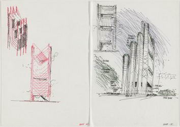
ایده ی بهینه کردن ارتباط میان سایه و نور طبیعی هدایت شده به درون فضای معماری،به شکل های جدید ممکن است. نور شکن های بزرگ پیش ساخته از بتن، که رنزوپیانو در مجموعه ی منیل در هوستون تگزاس استفاده کرد، نمودی زیبا از این اشکال تازه را به نمایش گذاشت.
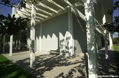
نورشکن های بتونی در مجموعه Menil - رنزو پیانو
نمونه ی دیگر، مرکز طراحی در لینز استرالیا، کار توماس هرتزوگ است. در این پروژه، از سیستمی استفاده شده است که قابلیت انعکاس و خنثی سازی پخش نور طبیعی را دارد.
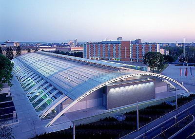
مرکز طراحی Linz در استرالیا - توماس هرتزوگ
شیشه، معماری قرون جدید را به شدت تحت تأثیر قرار داده است. اگر چه کاربرد این ماده ی ساختمانی در دهه های 50 و 60 قرن بیستم باعث بروز مشکلاتی شد، هنوز هم شیشه یکی از مصالح تضمین شده با کارایی خیلی خوب در معماری خورشیدی است.
جیمز کارپنتر، معمار و طراح شیشه و نور نیویورک، از شیشه دیاکرومیک برای ایجاد تأثیرات نوری استفاده کرده است. در مدلی که او برای کار در کلیسا پیشنهاد داده است، بیننده به محض مواجهه با اشکال هندسی ناشی از نور، به اهمیت این ایده و حضور آن به عنوان یک هدف از ابتدای شکل گیری طرح پی می برد. از آنجا که این برخورد الزاما به بهینه سازی در مصرف برق نمی انجامد، واضح است که جستجوی روش های جدید برای مطلوب کردن کاربرد شیشه به عنوان یک ماده ی ساختمانی مورد نیاز است.
شیشه الکتروکرومیک،دستاورد جالبی است که از طریق افزودن خواص متحرک به یک ماده ثابت به دست آمده است. شیشه ی الکتروکرومیک، با استفاده از جریان الکتریکی به مدت چند ثانیه می تواند به یک سطح کدر تغییر یابد.
ایده ی دیوار چند لایه ی تمام متحرک را، که مثل آفتاب پرست قادر به واکنش نسبت به محیط باشد، مایک دیویس از شرکت ریچارد راجرز دنبال کرد. مایک دیویس یک شخصیت پیش رو در کشف زمینه های جدید در تکنولوژی شیشه محسوب می شود. از فعالیت های او می توان به مطالعات متنوع در زمینه اولین نمونه های جداره های درخشان چند پوسته (multi-skin glazing) برای پروژه تحقیقی موسوم به پروژهء 218 اشاره کرد.
دیوار مجوف و قابل تهویه (ventilated cavity wall) جداره ی خارجی ساختمان لویدز لندن، در عین کارایی حرارتی بالا، نمونه دیگری است که نور طبیعی تلطیف شده را به شکل بهینه در اختیار فضاهای داخلی قرار می دهد.
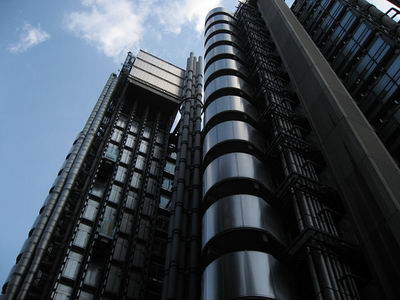
ساختمان لویدز لندن - ریچارد راجرز
یکی از زمینه های مناسب برای مطالعه و تحقیق، بررسی امکان کاربرد گازها، مایعات و حتی اجسام یا مواد ارگانیک است که می توان آنها را بین دو جداره ی شیشه یا به نحوی که به خود شیشه شکل دهند، استفاده کرد. به همان صورتی که در جام های شیشه در ساختمان لویدز لندن به کار رفته است.
هنر استفاده از نور طبیعی برای ایجاد تأثیرات نمایشی، هنوز هم یکی از موضوعات مورد توجه در معماری است. در این زمینه فناوری های جدید، امکانات جدیدی را پیش روی گذاشته اند.
ساختمان رایشتاگ برلین، محل مجلس جدید آلمان است که توسط نورمن فاستر و شرکاء اجرا شده است. ایده ی مبتکرانه این پروژه در مورد مسئله ی انرژی، نهایتا به سازه ای با نمود بیرونی در بالای ساختمان، با قابلیت هدایت نور انجامید. این تعبیر جدید از یک گنبد، که جایگاه بازدید کنندگان است، نور طبیعی را به واسطه ی صدها آینه ی تشکیل دهنده ی قیف میانی، به بخش زیرین ساختمان یعنی مجلس منعکس می کند.
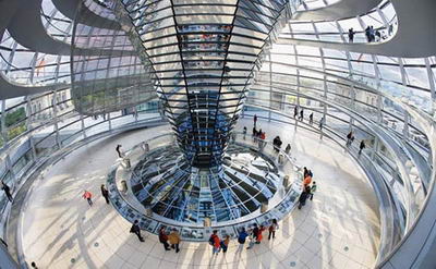
گنبد نورگیر مجلس رایشتاگ برلین
یکی
از اجزای شاخص بانک هنگ کنگ، کار دفتر فاستر، آتریوم تامین کننده ی نور
طبیعی در ساختمان است. تامین نور در این ساختمان از راه بازتاب نور از سطح
دو آینه ی بسیار بزرگ میسر شده است. صفحه ی جمع کننده ی نور آفتاب در
بیرون، از صدها آینه ی کوچک، که مسیر نور آفتاب را دنبال کرده و آن را به
سمت آینه ی مقعری در بالای آتریم می تابانند، تشکیل شده است.
این
آینه ی مقعر، نوررا به درون فضا و حتی زیر کف طبقه ی شیشه ای ساختمان
هدایت می کند. اسکیس اولیه ی نورمن فاسترف به بهترین شکل نحوه هدایت نور
به زیر زمین را نشان می دهد.
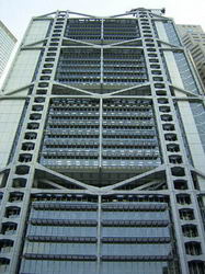
هدایت نور به طبقات پایینی بانک هنگ کنگ - اسکچ نورمن فاستر
باتری های خورشیدی:
نور
ملموس ترین انرژی تجدید پذیر است. امروزه روش های جدیدی از جمله (باتری
خورشیدی) برای تبدیل این انرژی به جریان برق در دسترس است. فیزیک دانی به
نام هنری بکرل کشف کرد که هنگام برخورد نور به ترکیبی از مواد حاوی
سیلیکون، ولتاژ الکتریکی تولید می شود. این کشف انقلابی به پیدایش این
نظریه که امکان تولید انرژی الکتریکی از نور طبیعی در فرآیندی شبیه به
فتوسنتز وجود دارد، انجامید.
با به کار گیری لایه های بسیار کم ضخامت از سیلیکون روی صفحاتی مثل شیشه یا صفحات فلزی هم، می توان به شکل های متفاوتی از باتری های خورشیدی دست یافت.
تولید سلول های باتری خورشیدی با سیلیکون کراپ (silicon crop)، که محصول جانبی از صنعت کامپیوتر است آغاز می شود، به نحوی که ابتدا آن را به صورت مذاب در می آورند، سپس آن را به شمش تبدیل کرده و نهایتا بلوک های تراش خورده را از ان می سازند. مرحله آخر کار برش این بلوک ها به صورت صفحات باریک به شکل ویفر خواهد بود.
باتری های کریستالی خورشیدی عموما به صورت صفحات باریک به شکل ویفر موجودند و برای محافظت، هنگام استفاده در فضای بیرون، آنها را در پوشش های پلاستیکی یا شیشه ای نگه می دارند. صفحات این باتری ها بر حسب نیاز مشتری می توانند با ابعاد یا خروجی های متغیر تولید شوند.
تمام محصولات ساخته شده برای فضا، از طریق انرژی خورشیدی و سلول های باتری خورشیدی (pv) تغذیه می شوند. در تلسکوپ هابل، از سلول های باتری خورشیدی غیر کریستالی با بالاترین میزان کارایی تا به امروز، استفاده شده است. اگر تلاش دانشمندان ناسا برای تامین نیروی مورد نیاز ماهواره ها و همچنین فضا پیماها نبود،چنین پیشرفت هایی در زمینه ی ساخت باتری خورشیدی (pv) به وجود نمی آمد. در طول بر نامه ی آپولولو، تکنولوژی تولید باتری خورشیدی دچار تحولات عظیمی شد. کارایی سلول های خورشیدی ازآن زمان تا کنون به چهار برابر افزایش یافته است.
صفحات باتری خورشیدی در حالت ایده آل باید مادامی که خورشید می تابد در معرض آن قرار گیرند. طبیعتا با تغییر جهت تابش خورشید این امر غیر ممکن می شود. اما امکان زاویه دادن به صفحات برای استقرار در بهترین جهت ممکن وجود دارد. همچنین نصب این صفحات به صورت خوابیده یا به شکل عمودی روی سقف یا نما وجود دارد. اما این امر تا حدی به کاهش کارایی و بازدهی باتری می انجامد.
استفاده از باتری خورشیدی با قرارگیری صفحاتی ازسلول های متنوع در کنار هم ممکن خواهد بود. این سلول ها می توانند با هر شکل و اندازه ای روی هم قرار گیرند. می توان از یک باتری خورشیدی برای تولید الکتریسیته در یک ماشین حساب استفاده کرد یا با ادغام هزاران صفحه ی باتری خورشیدی در کنار هم، مزرعه ای از باتری های خورشیدی ساخت.
کاربرد باتری خورشیدی در ساختمان، توجه معماران سراسر جهان را به خود جلب کرده است. در بسیاری از پروژه های موفق شناخته شده از صفحات باتری خورشیدی به عنوان قسمتی از سیستم پوشش یا نمای ساختمان استفاده شده است. استفاده از این مصالح جدید که ملزومات مخصوص به خود را به خصوص از نظر زاویه ی جهت اقتضا می کند، به مسئله ی طراحی ساختمان بدل شده است.
غرفه ی طراحی شده ی نیکلاس گریم شاو در نمایشگاه شهر سویلدر سال 1992، کاربرد جدید سلول های باتری خورشیدی را نشان می دهد. در این پروژه، سلول های باتری خورشیدی روی جمع کننده های سقفی با شکل های زیبا نصب شده است و علاوه بر سایه اندازی، نقش تامین نیروی لازم برای پمپاژ آب خنک کننده ی نمای ساختمان را بر عهده دارند.
از آنجا که
تولید سلول های باتری خورشیدی کم است، هزینه ی تولید آن بالاست. در صورتی
که تقاضا برای تولید این محصول افزایش پیدا کند، قیمت آن به میزان محسوس
کاهش می یابد. بسیاری از دولت ها در حال حاضر سوبسید هایی را برای افزایش
میزان تولید این محصول در نظر گرفته اند. در سال 1990 در آلمان برنامه ی
هزار سقف طرح ریزی شد. در ژاپن نیز در سال 1995 برنامه ی مشابهی تحت عنوان
هفتاد هزار سقف طرح ریزی شد.
از آخرین دستاورد های ژاپنی ها می توان
صفحات سقفی باتری خورشیدی غیر بلوری (amorphous) اشاره کرد. نمای متشکل از
باتری خورشیدی که برای بهبود برنامه انرژی رسانی در آخن (Aachen power
utilities) کشور آلمان با همکاری فلگسول صورت گرفت، از اولین نمونه های از
این دست در جهان محسوب می شود.
امکان کار گذاشتن ورقه های سلول های باتری خورشیدی بین دو ورقه شیشه، کاربرد جالب دیگری داردکه در آن بخشی از صفحه می تواند به عنوان وسیله ای برای ایجاد سایه عمل کند و اجازه ی عبور نور از شکاف های مابین سلول ها را فراهم سازد. تصویر کتابخانه ای که مشاهده می کنید، نشان می دهد که این تکنولوژی چگونه می تواند در معماری استفاده شود.
دفتر نورمن فاستر و شرکا با همکاری نوربرت کایرز، اولین نمونه های پرده های پوشیده شده از باتری خورشیدی را ارائه دادند. این پرده ها در ساختمان های قدیمی می توانند به عنوان شاتر های قابل تغییر یا پرده های کرکره ای متحرک کاربرد داشته باشند. کلیه قطعات سایه انداز به عنوان محلی برای نصب سلول های خورشیدی ایده آل هستند. چرا که ضمن قرار گیری در مقابل خورشید می توانند با تغییر مسیر نور در طول روز، جهت خود را تغییر دهند. برای این کار سیستم های کنترل کننده ی پیچیده با استفاده از کامپیوتر لازم است تا میزان استفاده از نور خورشید، سایه اندازی لازم و جمع آوری انرژی را اولویت بندی کند.
ادامه مطلب
| |||||

 Thin_Glass 4-Seiter
ادامه مطلب


-
Virbrating Screen
-
sandstone washing machine
-
Compound cone crusher
-
shanghai vibrating screen
-
spring cone crusher
-
jaw crusher
-
Supply crushing plant
-
Impact crusher spare parts
-
sand washing machine
-
Spring Cone Crusher
-
Cone Crusher
-
Supply shanghai donglong Screening Equipment
-
stone jaw crusher
-
cone crusher
-
Jaw Crushers


ادامه مطلب
By combining it’s engineering expertise with extensive experience in the procurement of proper materials and equipments most of which are made in China , Shanghai Pony Technology Co., Ltd. is capable to provide customers with solutions, offering products with highest quality but at an economically attractive cost.
Staff of Shanghai Pony Technology Co., Ltd. has developed close working relationships with International material and equipment suppliers, and will utilize such experiences when it becomes necessary. In addition, the top management of Shanghai Pony Technology Co., Ltd. has been associated with a large independent glass company, who has been providing constant supports.
Shanghai Pony Technology Co., Ltd's principles for construction of production line:
Balance between advanced technology and economical construction: Relying mainly on domestic materials and equipments with introduction of advanced systematic technologies in design, production and management, Shanghai Pony Technology Co., Ltd. strives to deliver our Clients with projects at international standards and minimum investment.
Combining advanced production monitoring, control systems, as well as reliable equipments: With sophisticated, reliable technologies for control systems and equipments, Shanghai Pony Technology Co., Ltd. provides the Client with the “tools” necessary to operate plants for high quality production..
Balance between project goals and proper allocation of materials and equipments: To meet client’s requirements , Shanghai Pony Technology Co., Ltd. selects the proper materials and equipments, compatible with both the economical and technical standards.
Balance between production and technical design: Design and production technologies, especially the compatibility of systematic management technology, are the keys to guarantee the quality of final products. Shanghai Pony Technology Co., Ltd. is staffed with experienced engineers and experienced plant operating personnel. This balance provides a practical design as well as the capability to provide our clients with ongoing technical supports.
Shanghai Pony technology Co. Ltd. relies on talents for sincere services.
BUSINESS SCOPE:
● Float glass
● Horizontally drawn glass
● Rolled glass
● Glass containers
● Glasswares
● Microcrystalline glass
● Glass block
● Automotive glass
● Functional glass
● New-type building materials
TECHNICAL FEATURES:
● Technology for end-fired furnaces with a daily melting capacity of 15 tons to 240 tons.
● Technology for float glass furnaces with a daily melting capacity of 15 tons to 1000 tons
● Forming and production technology for producing float glass at 1.1 mm to 25mm in thickness
● Installation/erection technology for production line, production
maintenance technology, quality control technology and production
management technology
● Technology for defects diagnosis and trouble shooting
● Technology for glass drain-off and furnace cold-down by proper temperature control
● Technical training and operation training
COOPERATION POTENTIAL
● Cooperate with international specialized companies for development
new technology, new process, new materials, new equipments and new
products.
● Turn key project
● Project sub-contracting service
● Process technology and technical supervision
● Put into production at required capacity and quality
● Online production technology service
● Package services starting from consultation, design, construction, production, research and development
ادامه مطلب

Express way gravel production technology
both asphalt and concrete pavement in the express way in the use of SMA or Superpave have strict requirement on the aggregate grain shape, especially in the basalt gravel content-Flake, but the former impact crushing processing technology can not meet the requirements, Hengchang metallurgical plant launched VI series of vertical impact crusher for crushing and shaping the screening process, which is widely applied in national Yong-Xian SMA express way.
Ultra-fine powder quartz sand, glass raw materials production line
Hengchang metallurgical building materials plant can produce full system of quartz sand production line equipments, and provide a full range of technical support. This production line equipment mainly includes vibration feeder, jaw crusher, silica plate straight barrel ball Mill (Bar-grinding ball mill) or High Aluminum-lining straight barrel ball mill, vibrating screen, plastic conveyer and other equipments. According to different requirements of different customers the process, various types of equipment can be provided.
New type glass raw materials processing technology advantages:
1, equipment investment is less than half of the other old type.
2, low metal consumption, main equipments includ rough jaw-crusher, it is used GFP series of negative Support, servicing life expectancy is more than six times long than PE Series crusher; Sand making machine is world fist choice for breaking the ablation materials, using the stone-crushing principle, its notable features is high broken efficiency, and low consumption of metal.
3, the new technology used dry production;


ادامه مطلب
شیشه فلوت عربستان با خرید از شرکتهای معتبر اروپایی دارای کیفیت فوق العاده شیشه است
Four months after beginning production, the Arabian United Float Glass
Company is already looking at expansion. Mishaal Al Orayer talks to Gay
Sutton about building a company through teamwork.
Located at Yanbu on the shores of the Red Sea, some 300km north of
Jeddah, Saudi Arabia, the Arabian United Float Glass Company (UFG) is
ideally positioned to supply top-quality glass into some of the most
rapidly growing regions of the world. With a small port literally on
its doorstep, and the major international port of Jeddah just down the
road, UFG has a global export reach. In the four months since it began
commercial operations, the company has not only been supplying
high-quality glass to Saudi Arabia and the surrounding nations, but
also exporting to Africa, Turkey, India and Singapore. And with
opportunities arising in new markets such as solar panel glass, it is
already examining the prospects for expansion.
The company was launched in June 2006 by the family-owned Meda
Industrial Group (MIG). “We investigated the glass industry in Saudi
Arabia and found that there was only one float glass plant, located in
the eastern part of country. Further studies showed there was a good
market for glass, and plenty of space for a second plant,” explains
managing director Mishaal Al Orayer.
Once the studies were complete, MIG began looking for suitable
investors. “We were fortunate enough to convince three publicly-listed
companies of the concept, the study and the feasibility of the
project.” The National Gas and Industrialisation Company, the National
Shipping Company and the Saudi Real Estate Company were the first to
make a commitment, quickly followed by Abdulrhman Al-Rashid & Sons
Group, a global construction and real estate company. The four
companies took a combined 70 per cent equity share in UFG, the
remaining 30 per cent being owned by MIG and other business people.
With the financial backing sorted, things progressed quickly. UFG was
formed in June 2006, and Shanghai Pony Technologies Company and
International Technology Consultants were soon brought in to design the
plant and the process. Construction began in March 2007 and just two
years later, on 15 February 2009, the plant began primary production,
followed by full commercial production in April.
The biggest challenge of the construction project, however, had been
the supply of gas. “We had been promised a natural gas pipeline by 2008
but this was delayed, and is now scheduled for 2010. So rather than
delay production, we made some modifications to the burners and set up
and stabilised the equipment to run on liquid petroleum gas. It was a
challenge, but it was successful.”
Setting up UFG has been a considerable achievement for Al Orayer, who
had previously worked in a local glass company associated with two of
the world’s largest float glass companies, Guardian Industries and
Saint-Gobain. UFG is the first float glass company anywhere in the
Middle East and Africa to be built and operated completely
independently of the five global float glass giants.
The company also has another interesting achievement under its belt.
Where many Saudi Arabian companies are usually set up with a 90 per
cent expatriate workforce and just 10 per cent drawn from the local
community, UFG’s workforce consists of 55 per cent local people and
only 45 per cent expats. “We currently employ 300 people in total. Only
fifty of those are experienced in the float process industry and only
135 are expatriates; the rest are local people who we have sent for
training to plants in Indonesia,” Al Orayer explains. "We eventually
expect to be able to reduce our manpower to 240, and we will continue
training our staff in the skills they require to become world-class
manufacturers.”
The manufacture of float glass requires knowledge, skills and
world-class equipment. The process works on the basis of floating a
layer of molten glass on a bath of molten tin. As the glass gradually
cools it achieves an even thickness and a very smooth surface on both
sides, producing high-quality glass that has many applications.
At Yanbu, the glass furnace covers an area of about 3,500 square metres
and extends 15 metres both below and above ground. Molten glass inside
the furnace is raised to an incredible 1600oC and then released under
gravity into the tin bath, where it spreads out and floats on the
molten tin. The glass is then slowly cooled to around 700oC. Rollers
transfer the glass to the annealing lehr (a specialised,
temperature-controlled kiln) where it is cooled to around 70oC under
highly controlled conditions to prevent the glass from stressing or
fracturing. Finally, the glass goes on to a state-of-the-art cutting
line and is cut to size before being packaged and shipped or stored in
the warehouse.
The plant consumes about 6.5 megawatts of power and has been equipped
with its own hydrogen and nitrogen plants—these gases are injected into
the tin bath to prevent oxidisation of the tin. The plant also has the
back-up of emergency diesel generators to guarantee continued power
supply should an interruption occur.
The equipment at Yanbu is state-of-the-art, and has been purchased from
around the world. The furnace and tin bath is a world-class design with
refractory and equipment from Europe and the US; the batch plant is
from Lhati of Finland; the annealing lehr comes from CNUD of Belgium
and the cutting line from Grenzebach of Germany.
Running at capacity, the plant will be capable of producing more than
600 tons of glass a day. The production figures show that some 10,000
tons were shipped in July—around two-thirds total capacity.
The marketing department is now looking to increase UFG’s share of the
market, and is currently exploring opportunities in the rapidly growing
solar panel sector. Meanwhile, UFG has plans for expansion of the
production facilities, the company having acquired a further plot of
land. “We’re seeking to expand the company with a second line which
will manufacture coloured glass. And we’re also looking at installing a
coating line alongside the first line.”
There are plenty of opportunities out there as the economy picks up, Al
Orayer believes, and the company is well positioned to supply into all
the major marketplaces. He explains that the excellent work
relationship with the chairman and the board of directors has created a
supportive environment, allowing the company to excel and making the
project a true success.
“This is a great achievement for Saudi Arabia, for me personally and
for our partners. We have built a company from nothing through team
work,” he says. “I have played football all my life and I have tried to
pass on to our staff the competitiveness and the team spirit of a
football team. We have had problems but we’ve managed to overcome them
through strong team spirit.”

|
|||||||||||||||||||||


.: Weblog Themes By Pichak :.